Wall flow type exhaust gas purification filter

a technology of exhaust gas purification filter and flow-type exhaust gas, which is applied in the direction of engines, mechanical equipment, machines/engines, etc., can solve the problems of easy cracking of parts and increased pressure loss at the initial stage, and achieve the effect of less pressure loss, effective crack prevention, and efficient collection of particulate matter

Active Publication Date: 2014-10-09
NGK INSULATORS LTD
View PDF6 Cites 47 Cited by
  • Summary
  • Abstract
  • Description
  • Claims
  • Application Information

AI Technical Summary

Benefits of technology

[0023]The present invention provides a wall flow type exhaust gas purification filter capable of efficiently collecting particulate matters contained in exhaust gas discharged from a direct-injection gasoline engine and a diesel engine for removal, and having less

Problems solved by technology

To increase the opening ratio of the inflow-side cells (inlet opening cells), however, means to relatively decrease the opening ratio of the outflow-side cells (outlet opening cells), and accordingly the pressure loss at the initial stage increases unf

Method used


Image

  • Wall flow type exhaust gas purification filter
  • Wall flow type exhaust gas purification filter
  • Wall flow type exhaust gas purification filter

Examples


example 1

[0052]As a ceramic raw material, silicon carbide (SiC) powder and metallic silicon (Si) powder were mixed at the mass ratio of 80:20. Hydroxypropylmethyl cellulose as binder and water-absorbable resin as a pore forming member were added to this mixed raw material, to which water was further added, thus manufacturing a forming raw material. Then, the obtained forming raw material was kneaded by a kneader, thus preparing a kneaded material.

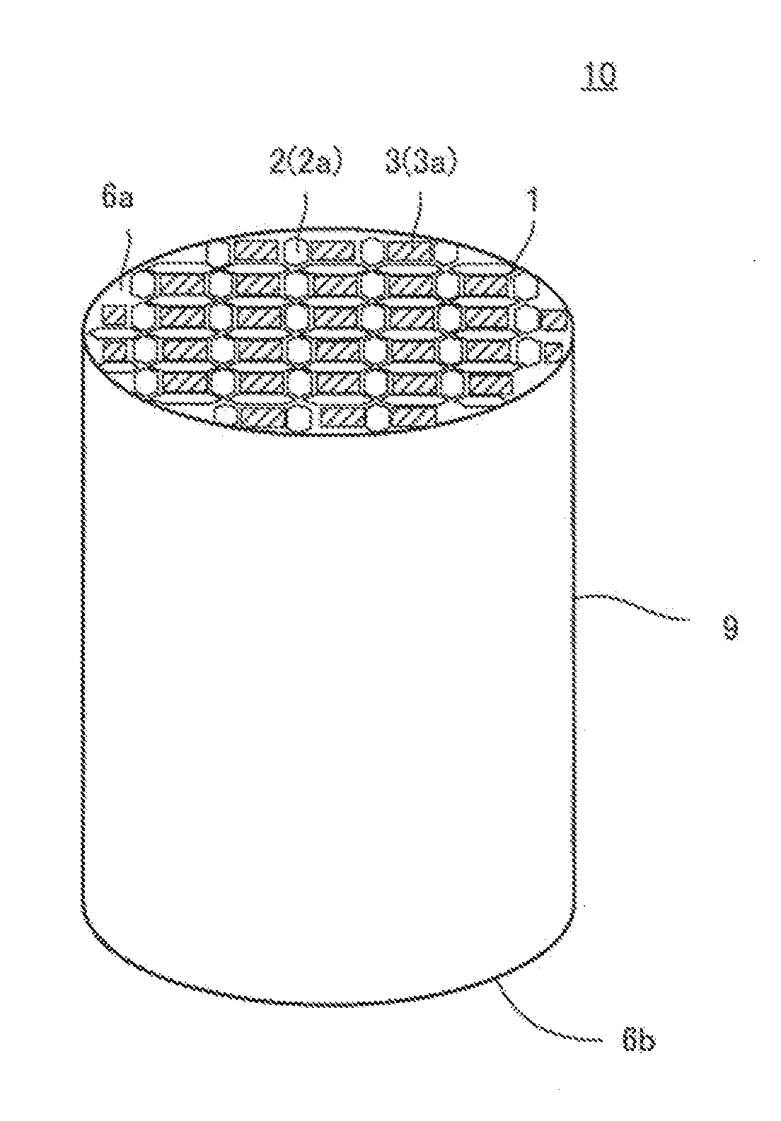
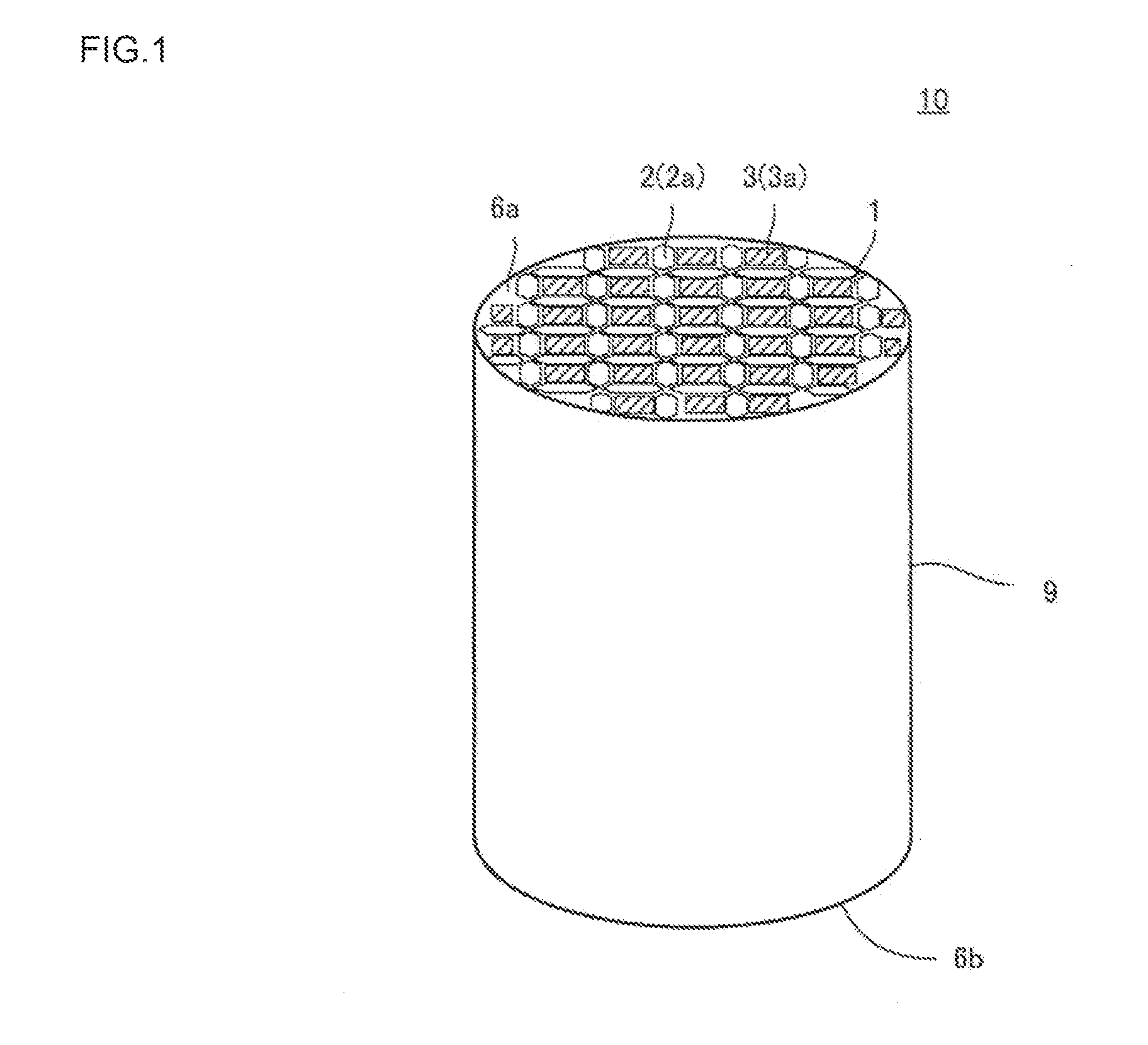
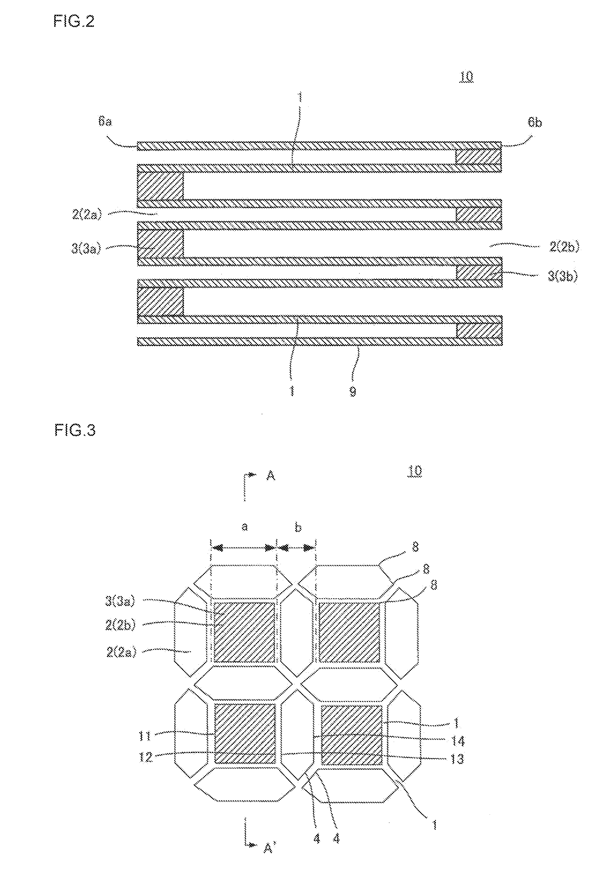
[0053]Next, the obtained kneaded material was formed by a vacuum extruder, whereby sixteen pieces of quadrangular prism-shaped honeycomb segments having a cell cross-sectional structure shown in FIGS. 3 and 4 were prepared. A honeycomb segment had a cross-section measuring 36 mm×36 mm and had a length of 152 mm. Distance a shown in FIG. 3 was 2.2 mm, and distance b was 1.76 mm. The partition walls had a thickness of 0.2 mm.

[0054]Subsequently the thus obtained honeycomb segments were dried by high-frequency dielectric heating and then dried at 120° C...

examples 2 to 24

Comparative Examples 1 to 4

[0059]Wall flow type exhaust gas purification filters 10 as Examples 2 to 24 and Comparative examples 1 to 4 were manufactured similarly to Example 1 except that distance a, distance b and the thickness of partition walls were set as shown in Table 1.

examples 26 to 51

Comparative Examples 9 to 15

[0069]Wall flow type exhaust gas purification filters 10 as Examples 26 to 51 and Comparative examples 9 to 15 were manufactured similarly to Example 25 except that distance a, distance b and the thickness of partition walls were set as shown in Table 2.

[0070]The wall flow type exhaust gas purification filters 10 as Examples 25 to 51 and Comparative examples 9 to 15 were attached to an exhaust pipe of a diesel engine, and pressure loss at the initial stage and pressure loss during PM accumulation were measured for evaluation. Table 2 shows the results.

TABLE 1Cell cross-InitialPMsectionalDividingDistance aDistance bCell pitchPartition wallpressureaccumulationCrackstructurewall[mm][mm]b / a[mm]thickness [mm]losspressure losslimitOverall ratingComp. Ex. 1FIGS. 3, 4No*2.41.920.80—0.2GoodBadGoodBadEx. 1FIGS. 3, 4No*2.21.760.80—0.2GoodAcceptableGoodGoodEx. 2FIGS. 3, 4No*21.60.80—0.2ExcellentAcceptableGoodGoodEx. 3FIGS. 3, 4No*1.81.440.80—0.2ExcellentAcceptableGoo...


PUM


Abstract

A wall flow type exhaust gas purification filter includes a honeycomb structure body and plugging portions. Four inlet opening cells having a substantially hexagonal shape in cross section surround one outlet opening cell having a substantially square shape in cross section, where one side of an inlet opening cell and one side of the outlet opening cell have a substantially same length and are substantially parallel and adjacent to each other. Distance a between the partition wall defining a first side of the outlet opening cell and the partition wall defining an opposed second side is in a range of exceeding 0.8 mm and less than 2.4 mm, and distance b between the partition wall defining a third side of the inlet opening cell and the partition wall defining an opposed fourth side has a ratio to the distance a in a range exceeding 0.4 and less than 1.1.

Description

[0001]The present application is an application based on JP-2013-078981 filed on Apr. 4, 2013 with the Japanese Patent Office, the entire contents of which are incorporated herein by reference.BACKGROUND OF THE INVENTION[0002]1. Field of the Invention[0003]The present invention relates to a wall flow type exhaust gas purification filter. More particularly, the present invention relates to a wall flow type exhaust gas purification filter suitably used for purifying of particulate matters and noxious gas components such as nitrogen oxide (NOx), carbon monoxide (CO), and hydrocarbon (HC) especially contained in exhaust gas from automobile engines.[0004]2. Background Art[0005]Reduction of fuel consumption by automobiles has been demanded in recent years from the viewpoints of influences on the global environment and resource saving. This leads to the tendency to use internal combustion engines having good heat efficiency such as a direct-injection gasoline engine and a diesel engine mor...

Claims


Application Information

Patent Timeline
IPC IPC(8): F01N3/022F01N3/035
CPCF01N3/035F01N3/0222F01N3/022F01N2330/34F01N2330/48
Inventor MIYAIRI, YUKIO
Owner NGK INSULATORS LTD
Why Eureka
Try Eureka