Series cooled module cooling fin

a cooling fin and module technology, applied in the field of cooling fins, can solve the problems of accelerated capacity fade and other undesirable cell conditions, premature aging, and prone to more complex ducting, and achieve optimal operating temperatures and temperature uniformity of cells, preserve the relative commonality of individual cell voltages, and increase the effect of disparities

Inactive Publication Date: 2014-10-16
GM GLOBAL TECH OPERATIONS LLC
View PDF3 Cites 20 Cited by
  • Summary
  • Abstract
  • Description
  • Claims
  • Application Information

AI Technical Summary

Benefits of technology

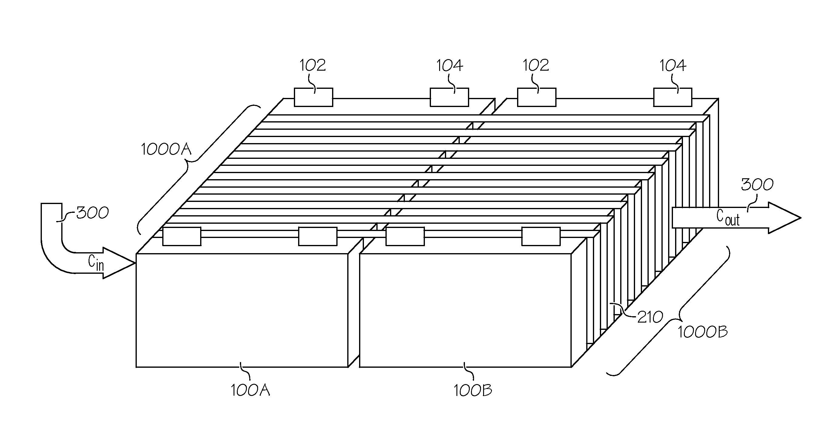
[0004]It is important for proper operation of a battery-based power system to keep operating voltages of the individual cells that make up the battery relatively close to one another. Likewise, because cell voltage drop is a function of resistance, and resistance is a function of temperature, it is desirable to keep the temperature of the cells close to one another in order to preserve this relative commonality of individual cell voltages. To this end, as well as to achieve a desirable balance between battery life and performance, the present inventors have determined that only small temperature variations between cells should be permitted. In one exemplary form based on current battery state-of-the-art, such differences should be (as mentioned above) kept to no more than about 5° Celsius, although subsequent improvements in cell technology may permit slightly larger disparities. Furthermore, the present inventors have determined that certain types of batteries—such as Li-ion batteries—operate best at temperatures between about 25° Celsius and about 40° Celsius. The cooling configuration of the present disclosure can be designed for a specific operating temperature that satisfies these requirements. As such, a battery cooling system based on the use of particularly-configured cooling fins can help maintain optimal operating temperatures and temperature uniformity of the cells within a battery under normal operating conditions, including minimizing heat differentials between neighboring cells. In both circumstances, this helps to mitigate thermal propagation and the related potential to damage additional components.

Problems solved by technology

Prolonged exposure to high temperature may lead to premature aging, accelerated capacity fade and other undesirable cell conditions.
Forced air and liquid cooling may prove to be effective at avoiding such excessive heat buildup in and around the individual cells that make up a larger battery pack, but in so doing may exacerbate excessive temperature differential between cells within the same module, section or pack where—for example—it is desirable to keep temperature differences between adjacent cells relatively small, often to no more than about 5° C. Furthermore, while parallel-based cooling systems typically are able to avoid significant temperature differentials (due in part to there being an equal chance for the cooling fluid to travel in each parallel path) of the overall system, they could be susceptible to more complex ducting in order to provide the necessary even flow distribution.

Method used


Image

  • Series cooled module cooling fin
  • Series cooled module cooling fin
  • Series cooled module cooling fin

Examples


Embodiment Construction

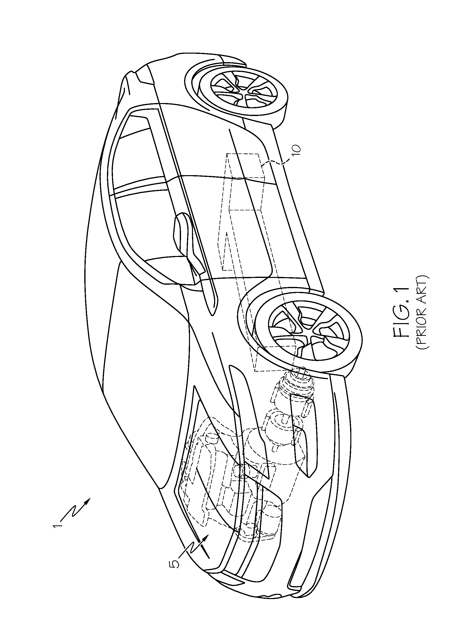
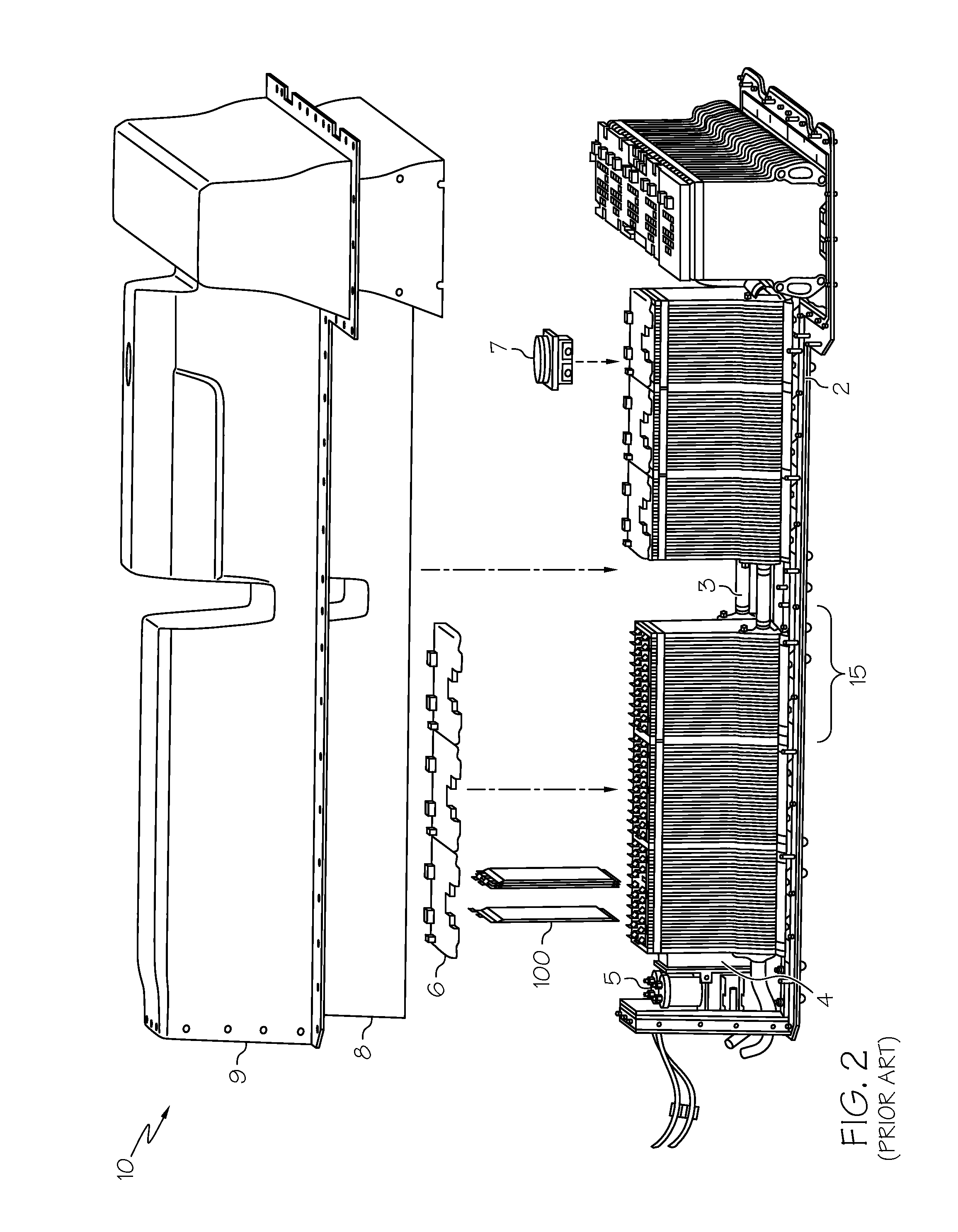
[0015]Referring first to FIGS. 1 and 2, a vehicle 1 including a hybrid propulsion system in the form of a battery pack 10 and a conventional ICE 5 in accordance with the prior art is shown. As mentioned above, such a vehicle 1 is known as an HEV. It will be further appreciated by those skilled in the art that vehicle 1 may not require an ICE 5; in such case, rather than being an HEV, it is an EV; either form is within the scope of the present invention. In the present context, the terms “battery cell”, “battery module” and “battery pack” (as well as their shortened variants “cell”, “module” and “pack”) are use to describe different levels of components of an overall battery-based power system, as well as their assembly. For example, numerous individual battery cells form the building blocks of battery modules (in conjunction with ancillary equipment) in turn make up the completed battery pack.

[0016]Referring with particularity to FIG. 2, battery pack 10 according to the prior art is...


PUM

PropertyMeasurementUnit
temperatureaaaaaaaaaa
heat rejectionaaaaaaaaaa
temperatureaaaaaaaaaa

Abstract

An automotive battery module with numerous battery cells and a series-based cooling fin arrangement placed in thermal communication with at least two of the battery cells. Heat generated within the battery cells by, among other things, electric current that can be used to provide motive power for the automobile, may be removed by the cooling fin that includes different portions tailored to remove relatively lesser or greater amounts of heat, depending on a potential temperature difference among the cells. The construction of the cooling fin is such that multiple heat transfer paths are established, each configured to convey heat away from the battery cells, as well as to keep temperature differences between adjacent series-cooled battery cells to a minimum. In one form, the multiple heat transfer paths may include a relatively laminar portion and a relatively turbulent portion, where in one form the increased turbulence may be obtained through numerous turbulators. Other such heat transfer paths may include an intermediate exhaust path, a discreet coolant channel or the like. Any or all of the turbulators, exhaust path or discreet coolant channel may be tuned in order to increase or decrease an amount of heat delivered to the cooling fin from the battery cells.

Description

BACKGROUND OF THE INVENTION[0001]This invention relates generally to a cooling fin to enable series cooling of individual battery cells and battery modules within a battery pack, and more particularly to using such a cooling fin without introducing large temperature differences or pressure drops.[0002]Lithium-ion and related batteries, collectively known as a rechargeable energy storage system (RESS), are being used in automotive applications as a way to supplement, in the case of hybrid electric vehicles (HEVs), or supplant, in the case of purely electric vehicles (EVs), conventional internal combustion engines (ICEs). The ability to passively store energy from stationary and portable sources, as well as from recaptured kinetic energy provided by the vehicle and its components, makes batteries ideal to serve as part of a propulsion system for cars, trucks, buses, motorcycles and related vehicular platforms. In the present context, a cell is a single electrochemical unit, whereas a ...

Claims


Application Information

Patent Timeline
Patent Type & Authority Applications(United States)
IPC IPC(8): H01M10/613H01M10/625H01M50/209H01M50/249
CPCH01M10/5016H01M10/5004B60L50/64B60L50/66B60L58/26B60L1/003B60L2240/545H01M2220/20H01M50/209H01M50/249Y02T90/16H01M10/625H01M10/6563H01M10/647H01M10/6557H01M10/6566H01M10/613Y02T10/70Y02E60/10
Inventor SCHROEDER, ELIZABETH A.HSU, CHIH-CHENGGUERIN, JOHN T.
Owner GM GLOBAL TECH OPERATIONS LLC
Why Eureka
Try Eureka