Starter provided with electromagnetic solenoid integrating rush current suppression function

a technology of electromagnetic solenoid and function, which is applied in the direction of engine starters, machines/engines, relays, etc., can solve the problems of large current flow (referred to as starting current or rush current), significant stress on the driver, and momentary stop of electric equipment such as meters, audio equipment or navigation systems, so as to reduce the heat generated by the sub solenoid being energized and avoid significant voltage drop of battery voltage , the effect of enhancing the robustness of the electromagnetic sol

Active Publication Date: 2014-10-23
DENSO CORP
View PDF29 Cites 10 Cited by
  • Summary
  • Abstract
  • Description
  • Claims
  • Application Information

AI Technical Summary

Benefits of technology

[0028]The electromagnetic solenoid according to the present disclosure regulates the movement of the second movable contact by operating the sub solenoid before the second switch is closed in response to an activation of the main solenoid, whereby the high resistive circuit path including the suppression resistor at the activation circuit of the motor can be formed. Thus, when the first switch is closed, the current flows through the suppression resistor so as to supply suppressed current to the motor. As a result, significant voltage drop of the battery voltage can be avoided. Moreover, since the operating time of the sub solenoid (i.e., corresponding to a period from when the regulation member is driven to be at the regulated position and to when the regulation member is released to be at the released position) is small, e.g., more than approx. 10 millisecond and up to approx. 200 milliseconds, heat generated by the sub solenoid being energized can be significantly reduced. Also, when the regulation member is driven to be at the regulated position thereby regulating the movement of the second movable contact, a movement of the plunger itself of the main solenoid is not regulated. Therefore, regulation force of the sub solenoid required for regulating the second movable contact does not necessarily exceed the force of the main electromagnetic solenoid being applied to the plunger 33, whereby the sub solenoid can be shrunk.
[0029]Further, while the sub solenoid is operating, that is, while the movement of the second movable contact is regulated by the regulating member, the second movable contact and the second fixed contact have not been contacted with each other. Hence, when the first switch is closed, since the current is supplied to the motor via the suppression resistor from the battery, significant voltage drop of the battery voltage due to rush current does not occur. In other words, the electromagnetic unit according to the present disclosure has a function serving a ICR relay conventionally used. As a result, influence of the voltage drop due to rush current is small so that the sub solenoid can be further shrunk. The sub solenoid has a configuration in which the plunger is pushed out when the second electromagnet is formed so as to drive the regulation member is driven to be at the regulated position. Accordingly, if a fault occurs in the sub solenoid, that is, the sub solenoid does not work even when power is supplied, the regulation member is not driven to be at the regulated position. In this case, the electromagnet solenoid can be operated as similarly to that of the non-ISS switch. Hence, even when a fault occurs in the sub solenoid, the fault does not immediately cause a malfunction of the starter operation. As a result, robustness of the electromagnetic solenoid can be enhanced.
[0030]Furthermore, the starter according to the present disclosure, since a function of the conventional ICR relay is integrated to the electromagnet solenoid, a harness that connects the starter and the ICR relay is not necessary, so that voltage drop at the harness (resistor-loss of the harness) becomes zero. As a result, compared to a case where the ICR relay and the starter are combined, the output capability of the starter can be enhanced. Also, the number of components is reduced so that system cost can be reduced and no areas for an ICR relay to be mounted are necessary so that the mountability of the starter is improved.

Problems solved by technology

In this respect, a problem arises that a large amount of current (referred to as starting current or rush current) flows when the motor is activated in response to the engine restart request after the idle stop operation is performed.
Specifically, when the large amount of current flows, the terminal voltage of the battery is greatly decreased so that instantaneous power failure occurs thereby causing momentary stop of the electric equipment such as meters, audio equipment or navigation system.
Generally, since the vehicle provided with the ISS performs the idle stop on the road, a large amount of current flows every time when the starter operates so that the driver may be stressed significantly from this phenomena.
However, since the ICR relay conventionally used is an individual component, it is necessary to prepare a signal line in order to operate the ICR relay and a harness to connect the ICR relay and the starter, so that necessary man-hours and the number of components are increased, thereby increasing the system cost.
Furthermore, since a fixing portion to fix the ICR relay is required to be disposed in the starter housing or other portion in the vehicle side, depending on types of vehicles, there is a difficulty to dispose the fixing portion in the vehicle.
As a result, necessary man-hours and the number of components are further increased so that the system cost will be increased.

Method used


Image

  • Starter provided with electromagnetic solenoid integrating rush current suppression function
  • Starter provided with electromagnetic solenoid integrating rush current suppression function
  • Starter provided with electromagnetic solenoid integrating rush current suppression function

Examples


first embodiment

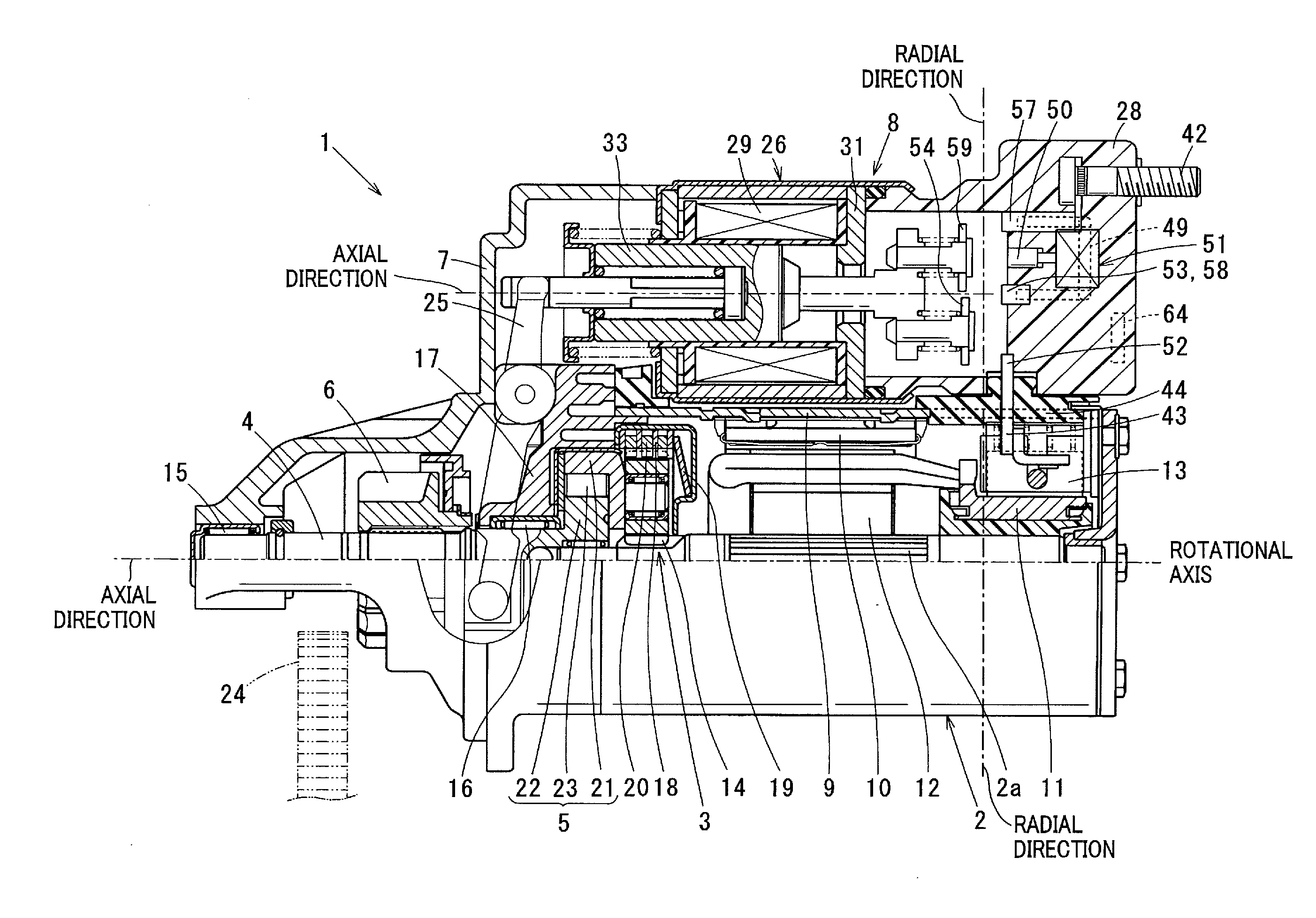
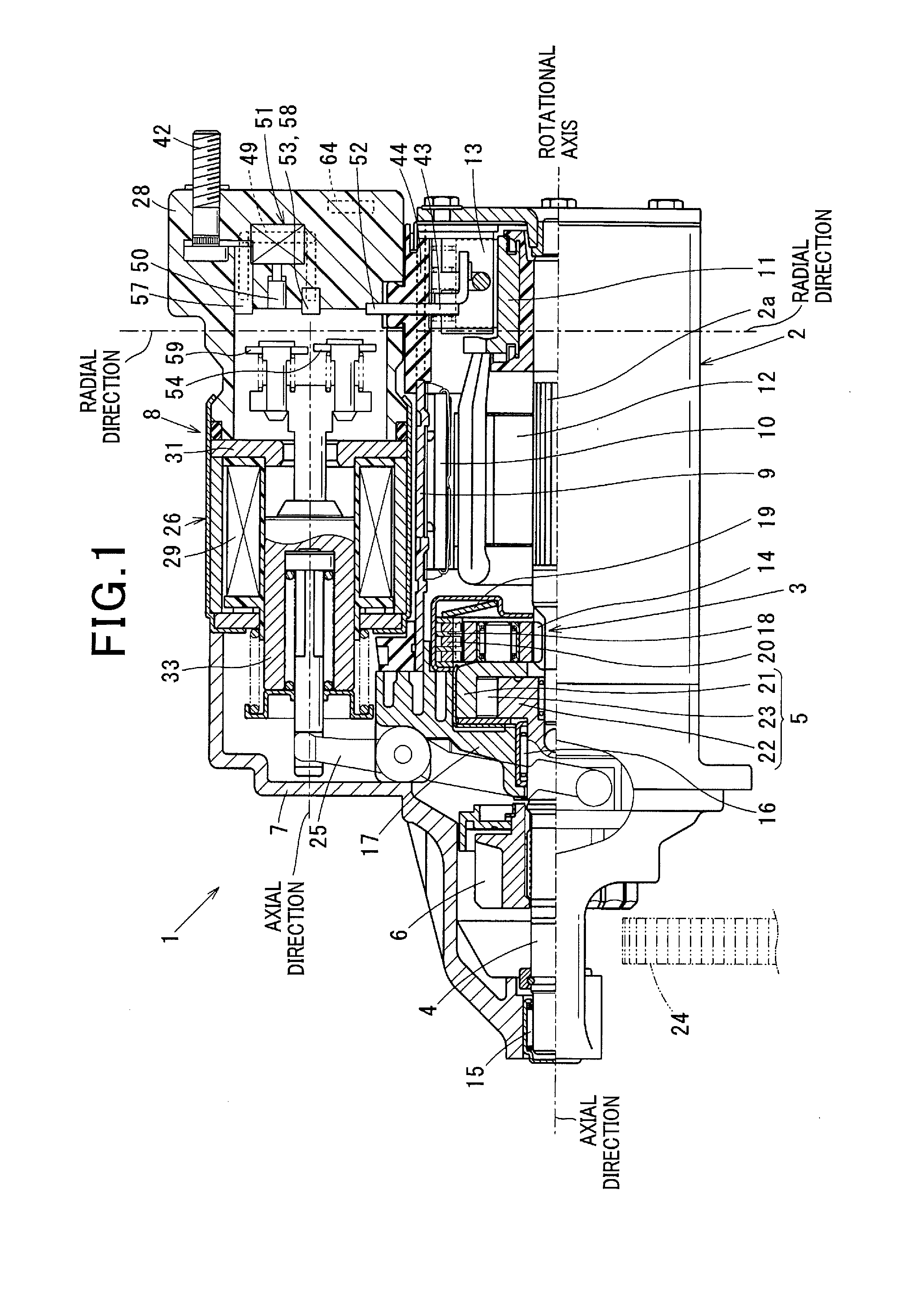
[0045]With reference to FIGS. 1 to 13, hereinafter is described the first embodiment.

[0046]As shown in FIG. 1, the starter 1 according to the first embodiment includes a commutator motor 2 that generates rotational force by being energized, a reduction unit 3 that reduces the rotational speed of the motor 2, an output shaft 4 coupled to an armature shaft 2a of the motor 2, an impact absorber (described later) that absorbs excessive impact propagated from the engine side, a clutch 5 that transmits torque generated by the motor 2 and amplified by the reduction unit 3 to the output shaft 4, a pinion 6 disposed on the output shaft 4 and an electromagnetic solenoid unit 8 fixed to a starter housing 7 together with the motor 2. The motor 2 and the electromagnetic solenoid unit 8 are fixed to the starter housing 7 to be in parallel to each other such that the rotational axis of (armature shaft 2a) the motor 2 and the longitudinal direction (axial direction) of the electromagnetic solenoid ...

second embodiment

[0083]According to the second embodiment, as shown in FIG. 11, the M terminal 43 has a bolt-shape similar to that of the B terminal 42 described in the first embodiment. In this case, regarding the small solenoid 51, the negative terminal side of the coil 62 can readily be connected to the M terminal 43 inside the switch cover 28 and can be connected to the ground (earth) from the M terminal 43 via the motor 2.

[0084]The IC 64 that controls the operating time of the small solenoid 51 is connected in series to the operation circuit of the small solenoid 51. In other words, the IC 64 is connected between the small solenoid 51 and the ground, or connected between the terminal-5037 and the small solenoid 51.

[0085]Regarding the M terminal 43 having bolt-shape according to the second embodiment, as similar to that of the conventional ISS switch or the non-ISS switch, a terminal of the motor lead (not shown) is connected to the male screw portion protruded from the backend of the switch cov...

third embodiment

[0086]According to the third embodiment, a structure is exemplified of the starter 1 in which the small solenoid 51 is connected to the M terminal 43 as similar to that of the second embodiment, and having longer operating life as similar to that of the brush 13. The starter 1 that uses the commutator motor 2 cannot accurately detect the operating life of the brush 13. Hence, the number of operating times is counted in the vehicle side and the ECU 48 prompts the user to exchange the starter 1 when the number of operating times reaches a predetermined value (life time operating count). In this case, since the brush 13 is designed to have enough margin in its operating life to meet the estimated operating life (i.e., not less than estimated operating times) of the starter 1, the brush 13 cannot be used effectively until around the operating life thereof.

[0087]Meanwhile, when the brush 13 wears to reach around the operating life, a contact pressure between the commutator 11 and the bru...


PUM


Abstract

An electromagnetic solenoid that controls a motor current of a starter includes: a first switch including a pair of first fixed contacts and a first movable contact, intermitting the motor current; a suppression resistor that suppresses the motor current; a second switch including a pair of second fixed contacts and a second movable contact, making a short circuit path to bypass the suppression resistor; a regulation member being driven by a sub solenoid, regulating the second switch being closed and releasing the second switch from being regulated after predetermined time elapses when a plunger is pulled by a main electromagnet. The regulation member is disposed between a regulated position and a released position to regulate the second switch.

Description

CROSS-REFERENCE TO RELATED APPLICATION[0001]This application is based on and claims the benefit of priority from earlier Japanese Patent Application No. 2013-90279 filed Apr. 23, 2013, the description of which is incorporated herein by reference.BACKGROUND[0002]1. Technical Field[0003]The present disclosure relates to a starter to start an engine mounted on a vehicle, and more particularly to a starter provided with an electromagnetic solenoid unit integrating a function in which rush current is suppressed when the motor of the starter is activated.[0004]2. Description of the Related Art[0005]Recently, to reduce carbon dioxide emissions and enhance fuel efficiency, vehicles provided with an idle stop system (hereinafter referred to ISS) that automatically stops and restarts the engine have been increased. Since vehicles having ISS stop the engine every time when the vehicles have to stop at the intersection due to red traffic lights or due to a traffic jam and restart the engine in ...

Claims


Application Information

Patent Timeline
Patent Type & Authority Applications(United States)
IPC IPC(8): F02N11/00
CPCF02N11/00F02N11/0851F02N11/087F02N15/067H01H50/543H01H51/065Y02T10/40
Inventor HIRABAYASHI, TAKASHI
Owner DENSO CORP
Why Eureka
Try Eureka