
Circuit for measuring the resonant frequency of nanoresonators

a nano-resonator and resonator technology, applied in the direction of sonic/ultrasonic/infrasonic wave material analysis, automatic control of pulses, etc., can solve the problem of bulk on the surface of the integrated circuit and corresponding costs, difficult to ensure a priori that the gain and phase conditions will be obtained that allow for spontaneous natural oscillation at the resonant frequency, etc. problem, to achieve the effect of reducing the necessary energy and power consumption resour

Active Publication Date: 2014-10-23
COMMISSARIAT A LENERGIE ATOMIQUE ET AUX ENERGIES ALTERNATIVES
View PDF3 Cites 15 Cited by
  • Summary
  • Abstract
  • Description
  • Claims
  • Application Information

AI Technical Summary

Benefits of technology

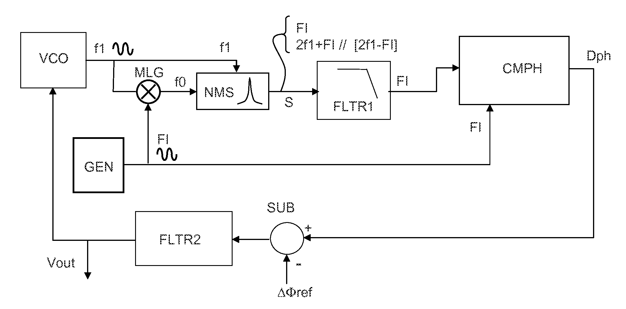
The invention aims to create a resonator circuit that consumes less energy and power while maintaining low phase noise. The frequency generator produces the intermediate frequency FI, which helps improve the purity of signals generated by the mixer and resonator. A direct digital frequency synthesizer is preferred, but a simpler clock circuit can also be used. Overall, the invention aims to enhance efficiency while maintaining high quality signal generation.

Problems solved by technology

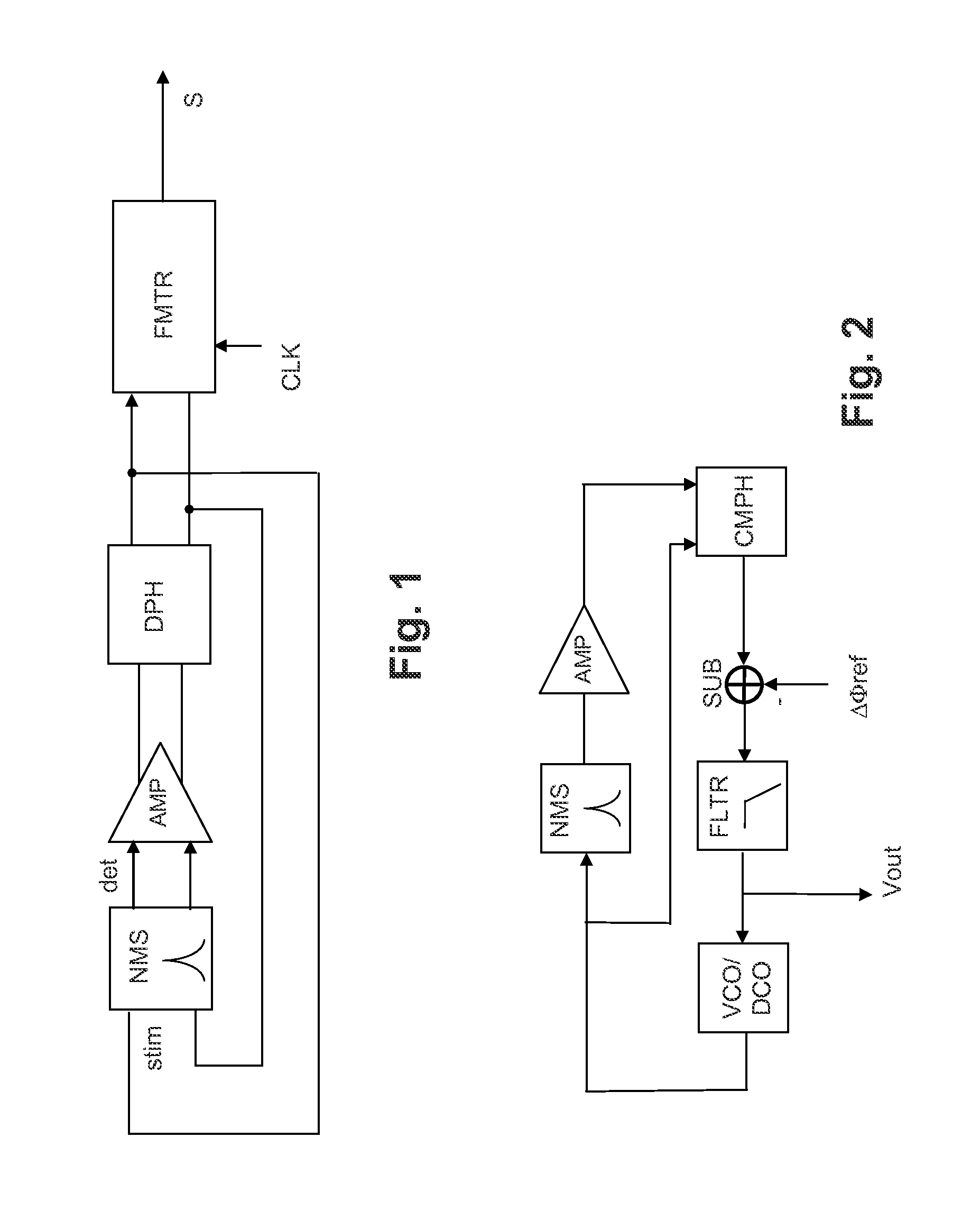
However, since there is a wide technological dispersion in the resonators and the components of the amplification subsystem, it is difficult to guarantee a priori that gain and phase conditions will be obtained that allow for a spontaneous natural oscillation at the resonant frequency.
However, the embodiment described is hard to implement because it requires two frequency synthesizers to establish the frequencies f0 and f1, and these two synthesizers must be frequency-adjustable with a high resolution, one because it ensures the locking of the excitation of the resonator, the other because it must be adjusted if one wishes for the synchronous detection at the resonator output to be achieved at a constant frequency.
The result thereof is bulk on the surface of the integrated circuit and corresponding costs and, also, high energy consumption.

Method used


Image

  • Circuit for measuring the resonant frequency of nanoresonators
  • Circuit for measuring the resonant frequency of nanoresonators
  • Circuit for measuring the resonant frequency of nanoresonators

Examples


Embodiment Construction

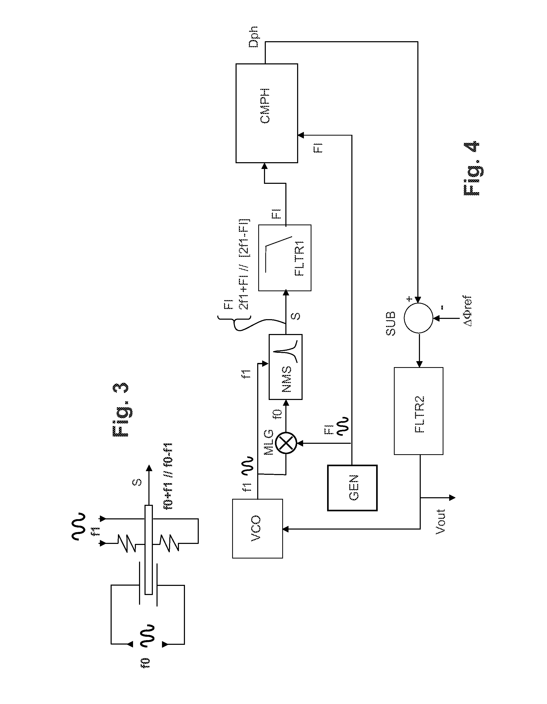
[0033]The nanoresonator used in the measurement circuit according to the invention is of the following type, whatever its practical embodiment: it possesses a vibration excitation input for receiving an actuation signal at an excitation frequency (f0), a polarization input for receiving a polarization signal having an AC component at a polarization frequency (f1), and finally an output for supplying an electrical signal representing the vibration of the nanoresonator. The polarization frequency serves to modulate the output signal to facilitate the measurement. The output signal, modulated by the polarization signal, comprises a component at an intermediate frequency which is the difference between the excitation frequency and the polarization frequency, as well as a component at a frequency that is the sum of these two frequencies. It is to this type of nanoresonator that the present invention generally applies. The component at the sum frequency will be eliminated by filtering. Th...


PUM


Abstract

In the field of nanoresonator oscillators or NEMS (nanoelectromechanical systems) oscillators, a circuit is proposed for measuring the oscillation frequency of a resonator, including a phase-locked loop with a frequency-controlled oscillator and a phase comparator. The resonator includes a vibration excitation input and a dynamic polarization input (using strain gauges). The frequency-controlled oscillator applies a polarization frequency f1 to the polarization input. A frequency generator supplies a fixed intermediate frequency FI; a mixer receives the frequencies f1 and FI for producing an excitation frequency f0 that is the sum or difference of f1 and FI. The phase comparator receives the frequency FI and the output signal of the resonator and produces a control signal that is sent to the frequency-controlled oscillator, indirectly locking the oscillation frequency onto the resonant frequency of the resonator.

Description

CROSS-REFERENCE TO RELATED APPLICATION[0001]This application claims priority to foreign French patent application No. FR 1353464, filed on Apr. 17, 2013, the disclosure of which is incorporated by reference in its entirety.FIELD OF THE INVENTION[0002]The invention relates to circuits with micro-machined electromechanical resonators and in particular to nanoresonator oscillators or NEMS (nanoelectromechanical systems) oscillators. These systems integrate, on one substrate, mechanical elements, micromachined to nanometre scale by collective microelectronics fabrication technologies.[0003]These circuits can be used notably for measuring very small weights, typically between 10−24 and 10−21 grams. The applications targeted are, for example, gas analysis or mass spectrometry.BACKGROUND[0004]In such systems that use resonators, the signal to be measured is the resonant frequency of the nanoresonator, in fact depending directly on the weight of matter deposited on the resonator or adsorbed...

Claims


Application Information

Patent Timeline
Patent Type & Authority Applications(United States)
IPC IPC(8): H03L7/093
CPCH03L7/093G01G3/16H03L7/02G01N29/22B82Y35/00G01N29/036H03B5/30
Inventor VILLARD, PATRICKBILLIOT, GERARD
Owner COMMISSARIAT A LENERGIE ATOMIQUE ET AUX ENERGIES ALTERNATIVES
Learn More