Grid-controlled x-ray source and space x-ray communication system and method

a x-ray source and grid control technology, applied in the field of space communication, can solve the problems of low signal-to-noise ratio, high low communication signal-to-noise ratio, etc., and achieve the effect of reducing the error rate of communication, improving the signal-to-noise ratio, and low error rate of communication

Active Publication Date: 2014-10-23
XI'AN INST OF OPTICS & FINE MECHANICS - CHINESE ACAD OF SCI
View PDF1 Cites 11 Cited by
  • Summary
  • Abstract
  • Description
  • Claims
  • Application Information

AI Technical Summary

Benefits of technology

[0048]2: The error rate of communication is low. The X ray is very weak during a long-distance communication because of scattering, so a high-sensitivity and large-area X-ray detector is adopted in the disclosure to improve the signal-to-noise and to reduce the error rate of communication.
[0049]3: The speed of communication is high. The X-ray detector adopted in the disclosure, which is an electric vacuum detector based on the MCP, utilizes external photoelectric effect which has a nanosecond response speed. However, the semiconductor detector adopted in the scheme of Dr. Keith Gendreau utilizes internal photoele

Problems solved by technology

1) The signal-to-noise ratio of communication is low and the error rate of communication is high: The photoelectric emission current of the photoelectric cathode is direct ratio to the power of incident light, but the photoelectric cathode will be subject to damage in perpetuity if the power of the incident light increases to a certain value, so that the current (Ia) cannot be too large. Therefore, in the scheme of Dr. Keith Gendreau, the transmission power (Ia*Va) of the modulated X-ray pulse source cannot be very large, accordingly, the communication signal-to-noise ratio is low and th

Method used


Image

  • Grid-controlled x-ray source and space x-ray communication system and method
  • Grid-controlled x-ray source and space x-ray communication system and method
  • Grid-controlled x-ray source and space x-ray communication system and method

Examples


Embodiment Construction

[0063]The disclosure discloses a space X-ray communication system, mainly including a transmitting apparatus and a receiving apparatus for X-ray communication, specifically as follows:

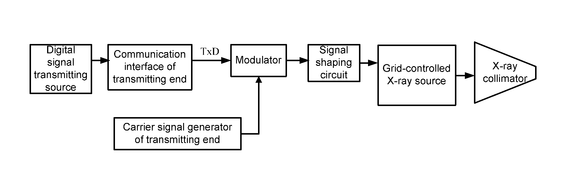
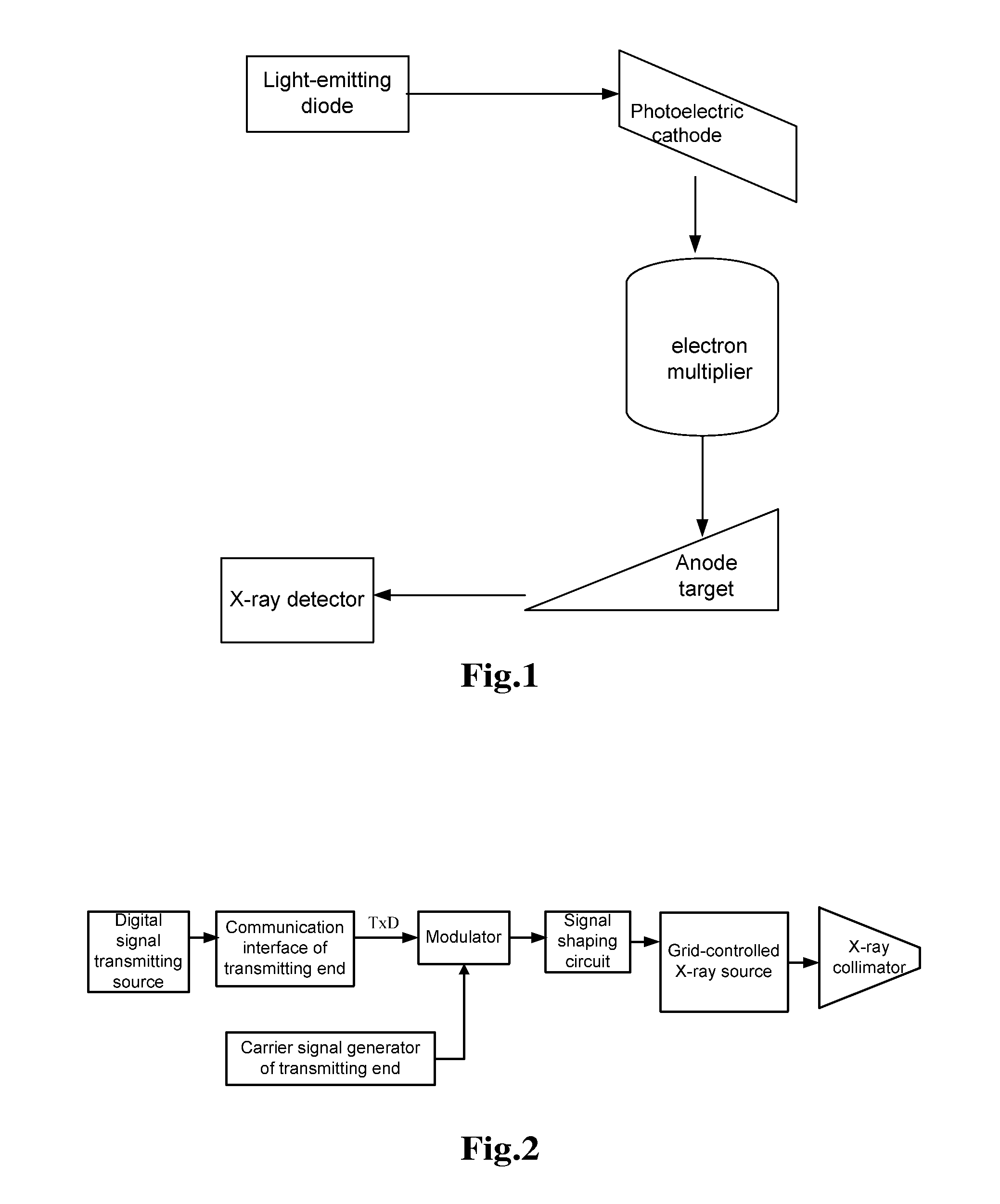
[0064]as shown in FIG. 2, the transmitting apparatus for X-ray communication is as follows:

[0065]an X-ray transmitter includes a digital signal transmitting source (a computer, a Single-Chip Microcomputer (SCM), a Field Programmable Gate Array (FPGA) or a Digital Signal Processor (DSP)), a communication interface of a transmitting end, a carrier signal generator of the transmitting end, a modulator, a signal shaping circuit, a grid-controlled X-ray source and an X-ray collimator; and the working principle is as follows: the digital signal transmitting source (the computer, the SCM, the FPGA or the DSP) inputs a digital signal to be transmitted into the modulator through the communication interface of the transmitting end (e.g., an RS232 interface, an RS485 interface, a USB2.0 interface, an LAN interfac...


PUM


Abstract

The disclosure relates to a grid-controlled X-ray source, a space X-ray communication system and a space X-ray communication method. The structure of the grid-controlled X-ray source is: one end of the filament is grounded and the other end is connected with the anode of a power supply, the thermionic cathode is located at the side of the filament and the emergence hole thereof faces the filament, the modulation grid is an electrode plate with a small hole which faces the emergence hole of the thermionic cathode, the electronic beam focusing electrode is located on the two sides of the small hole of the modulation grid to form a focusing channel facing the small hole, an electronic beam is focused by the electronic beam focusing electrode and then transmitted to the metallic target anode, wherein the transmitting surface of the metallic target anode faces the outlet of the focusing channel and the other surface is connected with the anode of the power supply, and the output window is located on an reflection path of the electronic beam which is from the metallic target anode. The disclosure solves the technical problems that the signal-to-noise ratio of communication is low, the error rate error rate of communication is high and the speed of communication is low when an X ray is used for implementing communication in the conventional art, and has the advantages of long communication distance and the low error rate of communication.

Description

FIELD OF THE INVENTION[0001]The disclosure relates to the technical field of space communication, in particular to a modulating pulse source and the key technology thereof in space X-ray communication.BACKGROUND OF THE INVENTION[0002]With very short wavelength and strong penetration capacity, an X ray can achieve a penetration rate of 100% at an atmospheric pressure of less than 10−4 Pa when the photon energy of the X ray is more than 10 keV (namely, the wavelength of that is less than 0.12 nm), which is nearly unattenuated transmission. That is to say, a long-distance space communication can be implemented by a very small transmission power. In another scenario, a satellite needs to pass through a plasma zone in which the radio wave is completely shielded when returning to the earth, but in the plasma zone, and then the satellite can pass through the plasma zone by the X-ray communication. Therefore, compared with other communication ways, the X-ray communication has the advantages...

Claims


Application Information

Patent Timeline
IPC IPC(8): H04B10/90H04B10/112H01J35/14
CPCH04B10/90H04B10/1123H01J35/14H01J31/49H01J35/045H04B10/118H01J35/147
Inventor ZHAO, BAOSHENGYAN, QIURONGSHENG, LIZHILIU, YONGAN
Owner XI'AN INST OF OPTICS & FINE MECHANICS - CHINESE ACAD OF SCI
Why Eureka
Try Eureka