Stereoscopic image display device, method for manufacturing same, method for reducing boundary variation, stereoscopic image display system, and patterned phase difference plate

a stereoscopic image and display device technology, applied in the manufacture of electric discharge tubes/lamps, instruments, polarising elements, etc., can solve the problems of inability to use existing liquid crystal cells, increase the size of black matrix of color filters, etc., and achieve the effect of reducing boundary variation and reducing crosstalk view angl

Inactive Publication Date: 2014-10-30
FUJIFILM CORP
View PDF0 Cites 4 Cited by
  • Summary
  • Abstract
  • Description
  • Claims
  • Application Information

AI Technical Summary

Benefits of technology

[0032]According to the invention, it is possible to provide a stereoscopic image display device contributing to the reduction of the crosstalk view angle in the vertical direction and the reduction of 3D boundary variation, a method for manufacturing the same, a method for reducing boundary variation, a stereoscopic image display system, and a patterned phase difference plate.

Problems solved by technology

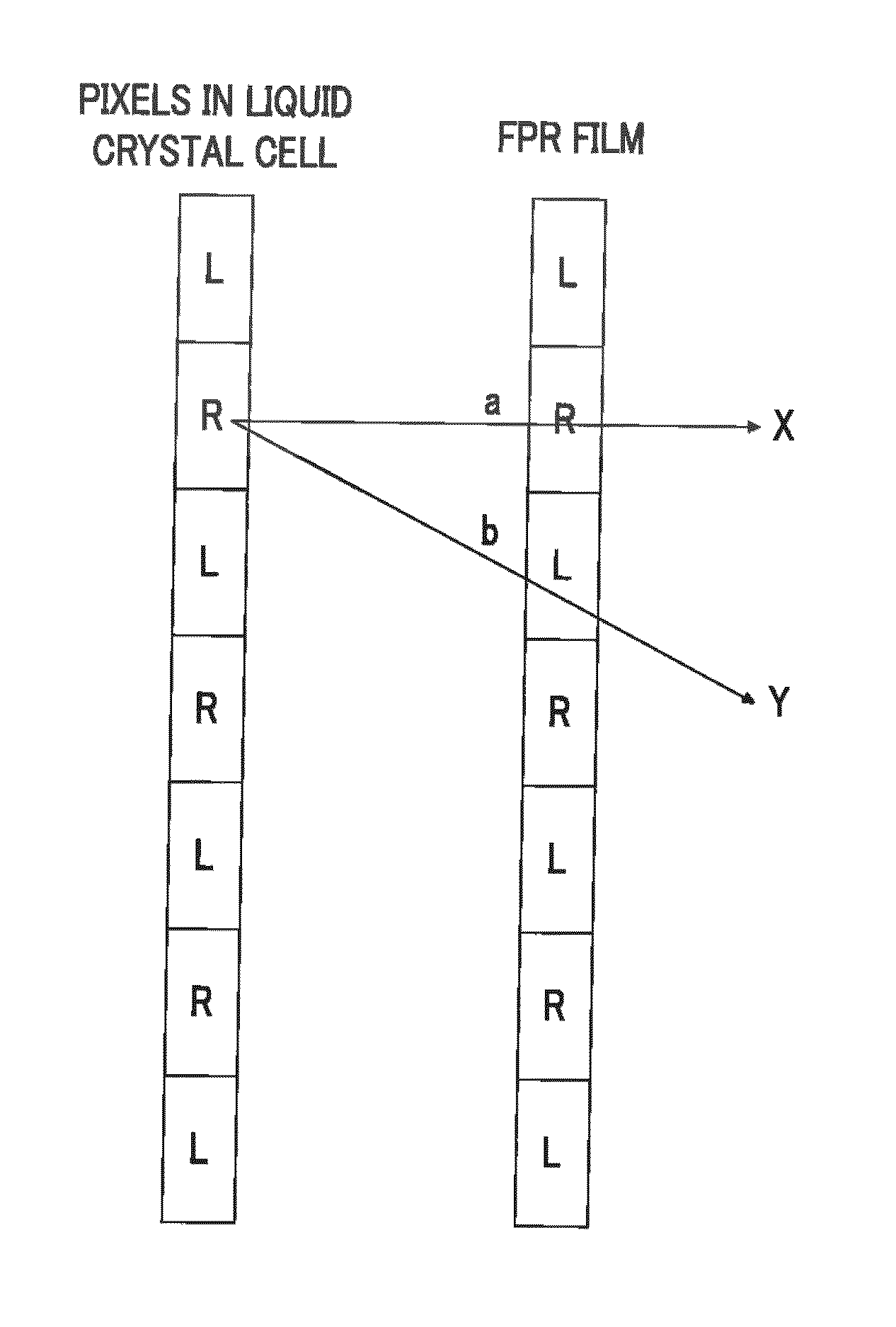
In the stereoscopic liquid crystal display device described in Kang et. al., while it is possible to reduce the above-described crosstalk, the size of the black matrix of the color filter is increased, and therefore it is necessary to revise the design of the entire liquid crystal cell, and there is a problem in that an existing liquid crystal cell cannot be used.

Method used


Image

  • Stereoscopic image display device, method for manufacturing same, method for reducing boundary variation, stereoscopic image display system, and patterned phase difference plate
  • Stereoscopic image display device, method for manufacturing same, method for reducing boundary variation, stereoscopic image display system, and patterned phase difference plate
  • Stereoscopic image display device, method for manufacturing same, method for reducing boundary variation, stereoscopic image display system, and patterned phase difference plate

Examples


example 1

Production of a Transparent Supporter a

[0170]The following composition was injected into a mixing tank, and stirred under heating so as to dissolve individual components, thereby preparing a cellulose acetate solution (dope C) having a solid content concentration of 22% by mass.

[0171](Composition of the Cellulose Acetate Solution)

Cellulose acetate having an acetylation degree in100 parts by mass a range of 60.7% to 61.1%Triphenyl phosphate (plasticizer)7.8 parts by massBiphenyl diphenyl phosphate (plasticizer)3.9 parts by massUltraviolet absorber (TINUVIN 3280.9 parts by massmanufactured by BASF Japan Ltd.)Ultraviolet absorber (TINUVIN 3260.2 parts by massmanufactured by BASF Japan Ltd.)Methylene chloride (first solvent)336 parts by mass Methanol (second solvent) 29 parts by mass1-butanol (third solvent) 11 parts by mass

[0172]A matting agent-added dope D was prepared by adding 0.02 parts by mass of silica particles having an average particle diameter of 16 nm (AEROSIL R972, manufact...


PUM


Abstract

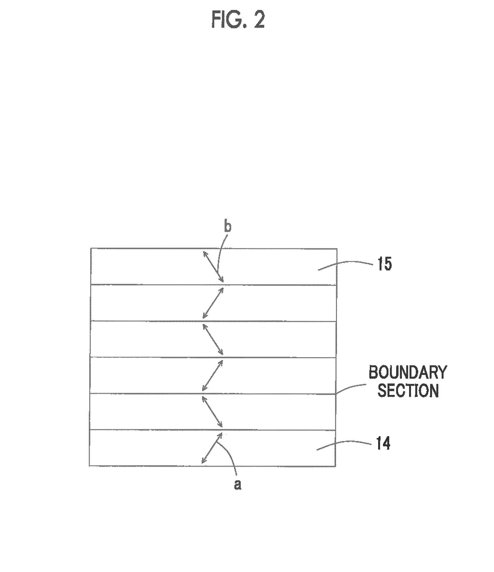
A stereoscopic image display device including at least an image display panel and a patterned phase difference plate disposed on an image-displaying side of the panel, the patterned phase difference plate includes at least a supporter and a patterned optical anisotropic layer having, on the supporter, first phase difference regions and second phase difference regions which are different in either or both an in-plane slow axis direction and a phase difference, and are alternately disposed in a stripe shape, and, in the supporter, a linearity, which is a meandering width in a direction perpendicular to a direction along the pattern of the patterned optical anisotropic layer, of an edge in a direction along a pattern of the patterned optical anisotropic layer is 0.0195% or less of a length in the direction perpendicular to the direction along the pattern of the patterned optical anisotropic layer in the image display panel.

Description

CROSS-REFERENCE TO RELATED APPLICATIONS[0001]This application is a Continuation of PCT International Application No. PCT / JP2013 / 056627 filed on Mar. 11, 2013, which claims priority under 35 U.S.C. §119(a) to Japanese Patent Application No. 2012-055215 filed Mar. 13, 2012, and Japanese Patent Application No. 2013-044062 filed Mar. 6, 2013, all of which are hereby expressly incorporated by reference into the present application.BACKGROUND OF THE INVENTION[0002]1. Field of the Invention[0003]The present invention relates to a stereoscopic image display device, a method for manufacturing the same, a method for reducing boundary variation, a stereoscopic image display system, and a patterned phase difference plate.[0004]2. Description of the Related Art[0005]In a stereoscopic (3D) image display device displaying a stereoscopic image, an optical member is required to turn an image for the right eye and an image for the left eye into, for example, circularly-polarized images in mutually op...

Claims


Application Information

Patent Timeline
Patent Type & Authority Applications(United States)
IPC IPC(8): G02B27/26G02B5/30G02B30/25
CPCG02B5/3083G02B27/26G03B35/26H04N2213/001H04N13/337G02B30/25G02F1/133631H04N13/30G02B5/30G02F1/13G02B30/00G02B30/27
Inventor ISHIGURO, MAKOTOOBA, TAKAHIRO
Owner FUJIFILM CORP
Why Eureka
Try Eureka