
Method of patterning a device

Inactive Publication Date: 2014-10-30
ORTHOGONAL
View PDF3 Cites 36 Cited by
  • Summary
  • Abstract
  • Description
  • Claims
  • Application Information

AI Technical Summary

Benefits of technology

The patent describes the use of a mixture of solvents in a developing and stripping solution to improve development and recycling performance in a photolithographic process. By using different ratios of the solvents, the solution becomes more effective in removing the photopolymer and reducing waste. This simplifies the recycling process and reduces manufacturing costs, while also minimizing the impact on the environment.

Problems solved by technology

Although the use of photoresists is routine in traditional electronic devices based on inorganic materials, photolithography has been difficult to achieve for devices using organic materials, thereby hindering the development of devices based on these materials.
Specifically, organic materials are much less resistant to the solvents that are used for conventional photolithography, as well as to the intense light sources that are sometimes used in these processes, with the result that conventional lithographic solvents and processes tend to degrade organic electronics.
Although there have been various attempts to overcome these problems, e.g., by ink jet printing or shadow mask deposition, these alternative methods do not produce the same results as would be obtained with successful photolithography.
Specifically, neither ink jet printing nor shadow mask deposition can achieve the fine pattern resolutions that can be obtained by conventional lithography, with ink-jet printing limited to resolutions of approximately 10-20 μm and shadow mask deposition to resolutions of about 25-30 μm.
Although these disclosures demonstrate good progress, many of the more useful fluorinated solvents can be expensive.
Distillation is mentioned, but it is noted that sufficient purity is difficult to achieve with distiller sizes typically used in a normal cleaning apparatus.
Although the recycling method of Nakazato may help purify the fluorine-based solvents of other materials, it will not separate different fluorinated solvents.
Ishiduka does not disclose using hydrofluoroether solvents as developers nor recycling mixtures of developer and stripping solvents.

Method used


Image

  • Method of patterning a device
  • Method of patterning a device
  • Method of patterning a device

Examples


embodiment 1

General Embodiment 1

[0062]In this embodiment, the first solvent is one that has a high degree of discrimination between solubilizing exposed and unexposed regions of the photoresist layer. Typically, the first solvent dissolves the unexposed regions at a moderate rate, but dissolves the exposed (switched) region at a much lower rate, preferably at least 10× lower. This helps produce an image with reasonable contrast and tolerable processing latitude, but an image may take longer than desired to develop appropriately. The second solvent is one that dissolves the unexposed regions at a rate greater than the first solvent rate, and preferably, also dissolves the exposed regions a rate higher than the first solvent rate. That is, the second solvent is generally a stronger solvent than the first solvent for both exposed and unexposed areas. Both should be selected to have a low interaction with sensitive, active organic materials if present during processing. Preferably the first and sec...

embodiment 2

General Embodiment 2

[0064]Here, the first solvent is one that has a high degree of discrimination between solubilizing exposed and unexposed regions of photoresist layer. Typically, the first solvent dissolves the unexposed regions at a moderate rate, but dissolves the exposed (switched) region at a much lower rate, preferably at least 10× lower. This helps produce an image having reasonable contrast and with good processing latitude, but an image may sometimes take longer than desired to develop appropriately. The second solvent in this embodiment is one that has higher solubilizing power than the first solvent with respect to removing the unexposed regions, but generally lacks sufficient solubilizing power to dissolve the exposed photoresists alone. For example, the first solvent, although it shows some development and good discrimination, may be too slow to be practical on its own. Conversely, the second solvent may be too fast to control, and although it is not capable of stripp...

embodiment 3

General Embodiment 3

[0066]Here, the first solvent generally provides low solubilizing strength with respect to both the exposed and unexposed regions of the photoresist. The second solvent is one that can solubilize both exposed and unexposed portions, but has a higher dissolution rate for the unexposed portions. When sufficient second solvent is added to the first solvent, the developing solution is capable of selectively solubilizing unexposed regions, i.e., dissolving unexposed regions at a rate that is at least 10 times higher than solubilization of the exposed areas. In this embodiment, the volume percentage of the second solvent is in a range from 20 to 80%, preferably 25 to 60%. The stripping solution will include the second solvent, optionally with a small amount of the first solvent or protic solvent or both. The volume of the second solvent in the stripping solution in this embodiment is at least 80%, preferably at least 90%.

[0067]An advantage of certain embodiments of the...


PUM


Abstract

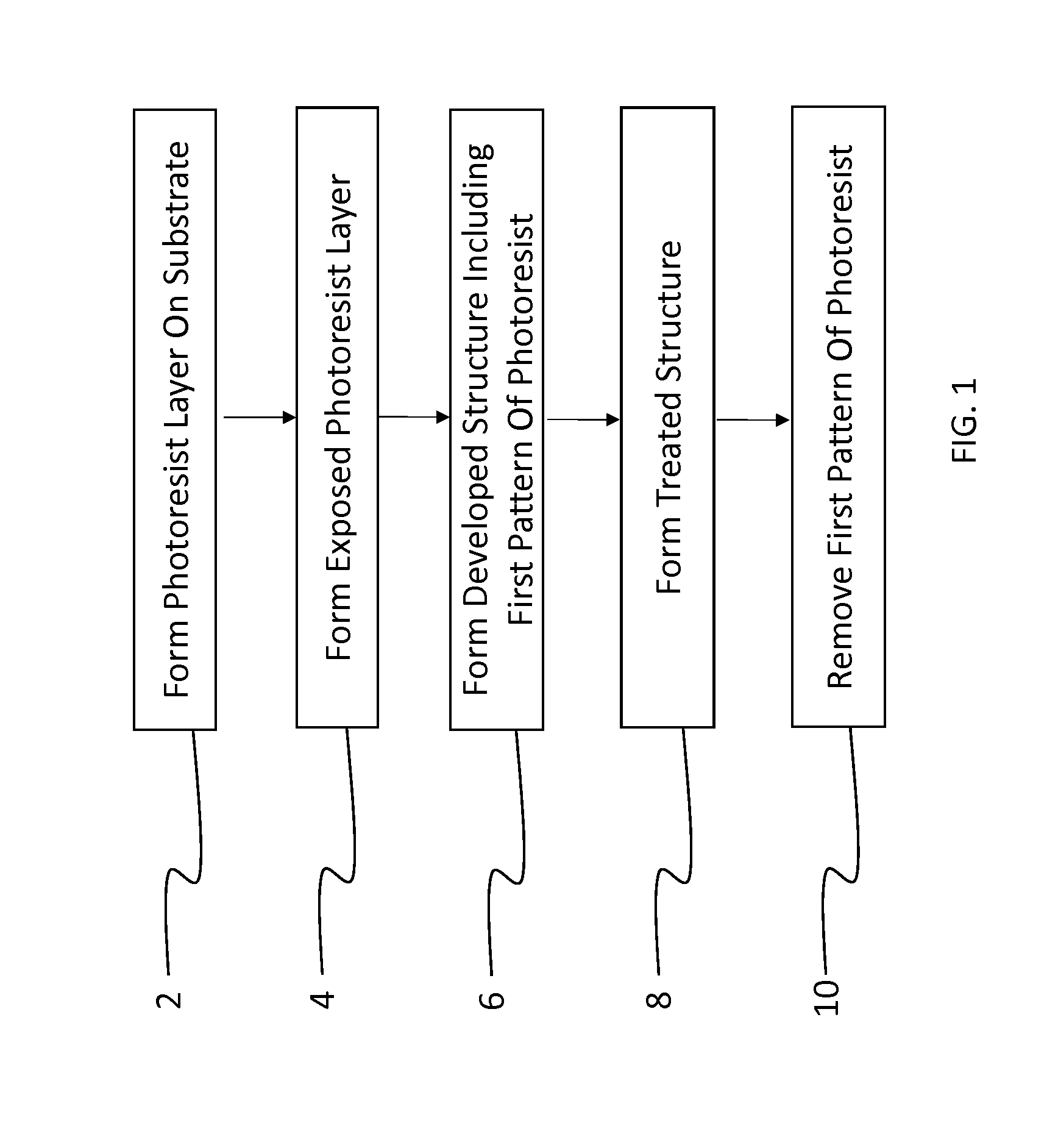
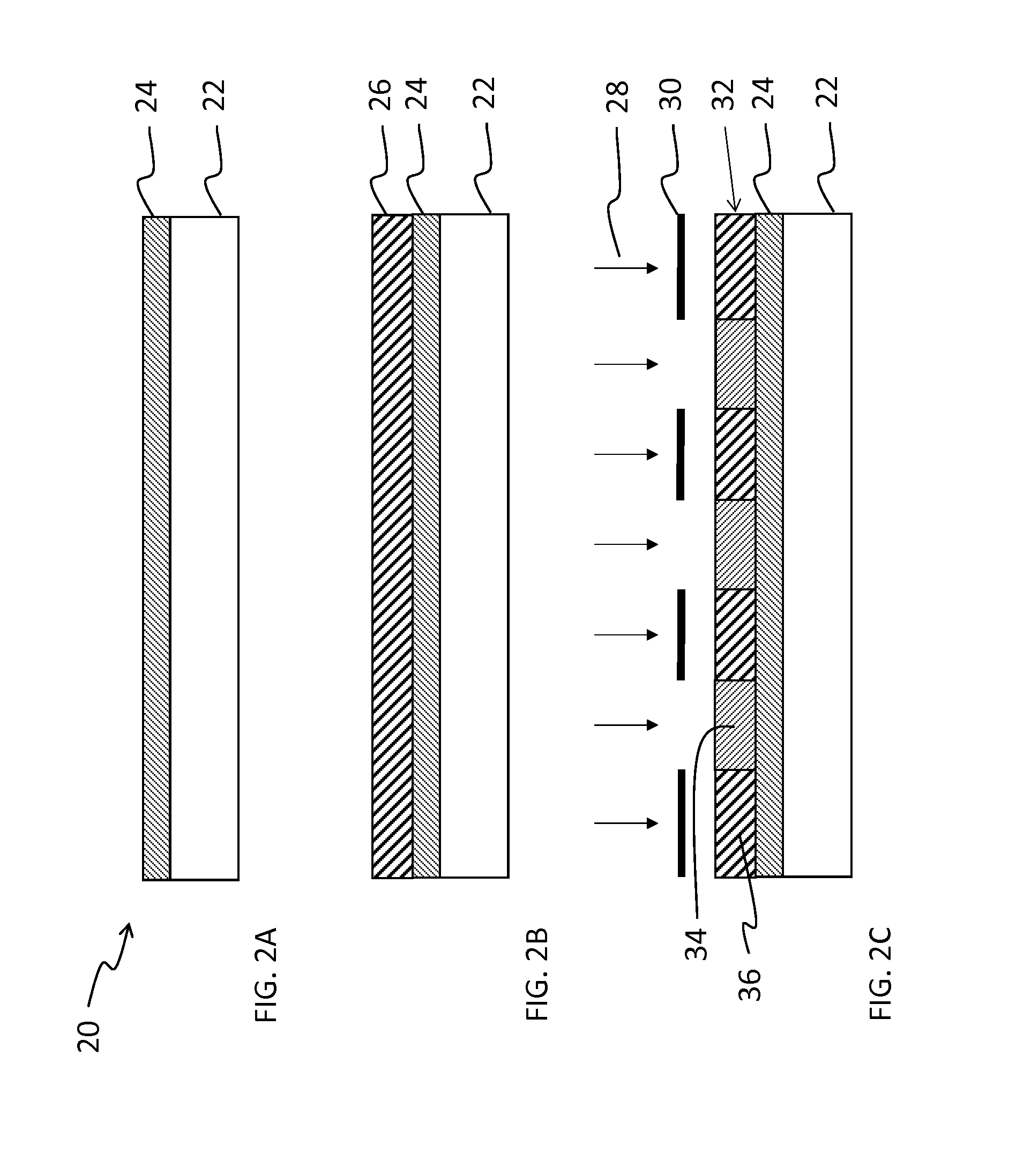
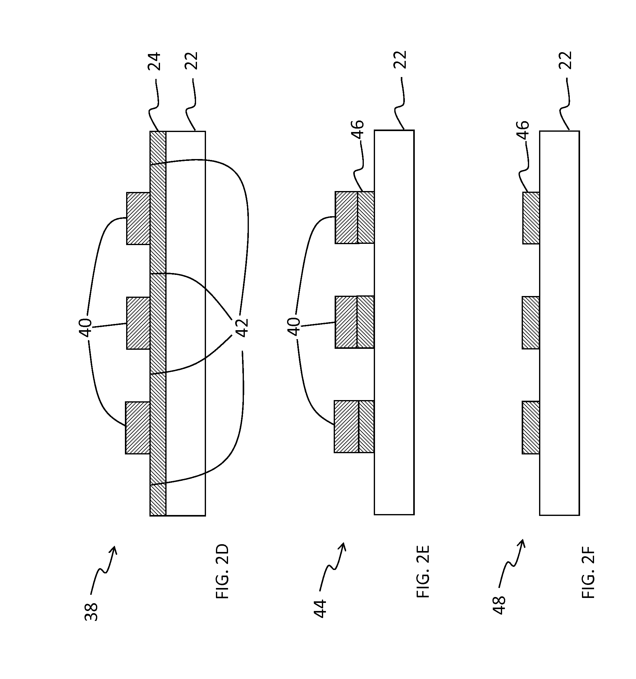
A photoresist layer comprising a fluorinated photoresist material is formed on a device substrate and exposed to patterned radiation. The exposed photoresist layer is contacted with a developing agent to remove a portion of the exposed photoresist layer in accordance with the patterned light, thereby forming a developed structure having a first pattern of photoresist covering the substrate and a complementary second pattern of uncovered substrate corresponding to the removed portion of photoresist, the developing agent comprising a mixture of first and second fluorinated solvents, wherein at least one of the first and second solvents is a hydrofluoroether. The developed structure is treated to form a treated structure. The treated structure is contacted with a stripping agent to remove the first pattern of photoresist, the stripping agent comprising at least the first or second solvent in a concentration different from the developing agent.

Description

CROSS-REFERENCE TO RELATED APPLICATIONS[0001]This application claims the benefit of U.S. Provisional Application No. 61 / 815,465, filed on Apr. 24, 2013, the entire disclosure of which is hereby incorporated herein by reference. This application is also related to U.S. patent application Ser. No. ______ entitled “Method of Patterning a Device,” Attorney Docket No. 16480.0012USU2, filed on even date herewith.STATEMENT REGARDING FEDERALLY-SPONSORED RESEARCH OR DEVELOPMENT[0002]This invention was made with Government support under SBIR Phase II Grant No. 1058509 awarded by the National Science Foundation (NSF). The government may have certain rights in the invention.BACKGROUND[0003]1. Field of the Invention[0004]The present invention relates to the use of fluorinated solvents and solvent blends for processing fluorinated photoresists. Such solvents and photoresists are particularly useful for patterning organic electronic and biological materials.[0005]2. Discussion of Related Art[0006]...

Claims


Application Information

Patent Timeline
IPC IPC(8): G03F7/40
CPCG03F7/40G03F7/038G03F7/422G03F7/20G03F7/0046G03F7/0392G03F7/0397G03F7/325G03F7/426
Inventor WRIGHT, CHARLES WARRENFREEMAN, DIANE CAROLBYRNE, FRANK XAVIERDEFRANCO, JOHN ANDREW
Owner ORTHOGONAL
Learn More