Medical instrument for inserting a chest drainage tube

a technology for insertion of chest drainage tubes and medical instruments, which is applied in the field of medical instruments, can solve the problems of never further advanced, and achieve the effect of convenient and rapid operation, less time-consuming

Active Publication Date: 2014-10-30
HILL DAVID A
View PDF6 Cites 12 Cited by
  • Summary
  • Abstract
  • Description
  • Claims
  • Application Information

AI Technical Summary

Benefits of technology

[0011]The conventional procedure for inserting a chest drainage tube into the pleural cavity requires significant manual dexterity for the surgeon to use his / her finger and a clamp to manipulate the chest drainage tube into place. This procedure may be more or less time-consuming depending upon innumerable factors. By using the instrument described herein, the insertion of the chest drainage tube is primarily a mechanical function easily and rapidly performed. The instrument circumscribes the chest drainage tube during insertion and includes a tip for penetration after insertion through the initial incision. A ramp at the distal end of the chest drainage tube causes the chest drainage tube to bend into alignment with the pleural cavity upon sliding movement of the chest drainage tube through the instrument. After placement of the chest drainage tube, the instrument is withdrawn and opened to accommodate lateral withdrawal of the chest drainage tube from within the instrument. Subsequently, the chest drainage tube may be sutured in place.

Problems solved by technology

It is never further advanced due to the risk of introducing skin contaminants into the chest.

Method used


Image

  • Medical instrument for inserting a chest drainage tube
  • Medical instrument for inserting a chest drainage tube
  • Medical instrument for inserting a chest drainage tube

Examples


Embodiment Construction

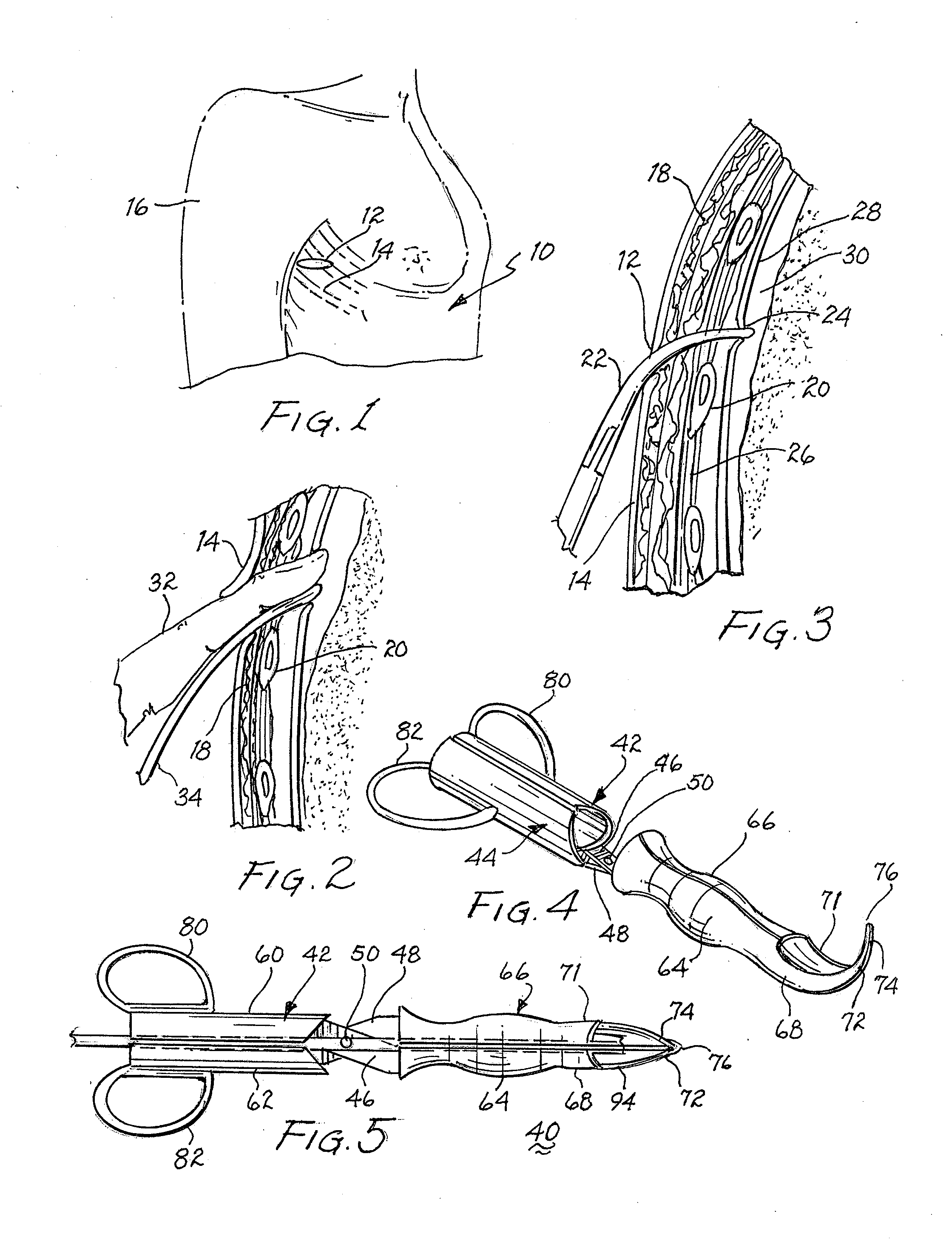
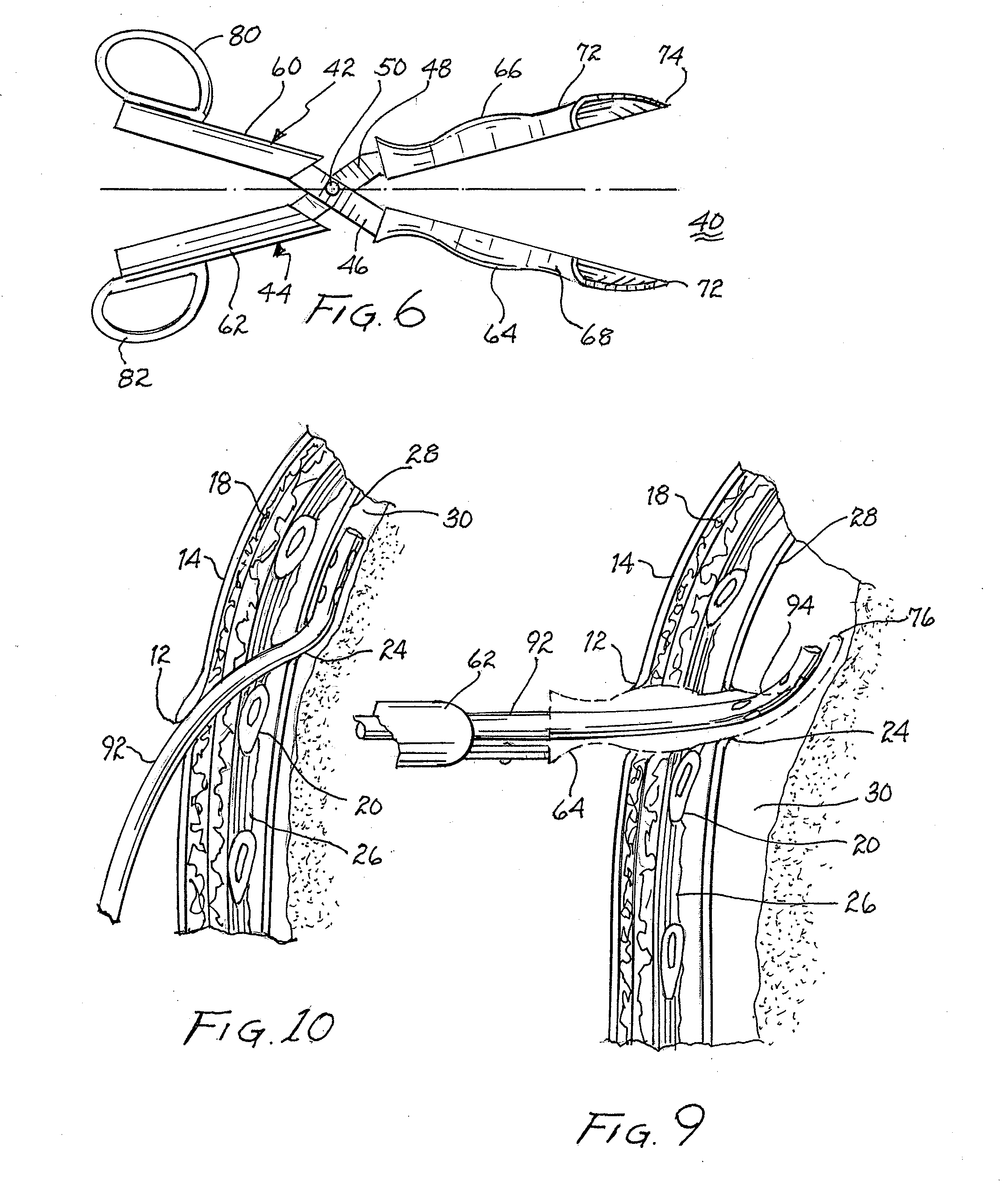
[0031]Referring to FIGS. 1 and 2, there is shown a torso 10 of a man prior to insertion of a chest drainage tube in the pleural cavity. An incision 12 is made through skin 14 at the level of the fifth intercostal space overlying the sixth rib. The incision is made just anterior of the mid-axillary line in a horizontal fashion. The patient's arm 16 is elevated above the patient's head to allow for adequate access. The incision is 3 cm in length after injection of local anesthetic into skin 14, subcutaneous tissue 18, and just above rib 20. Once this is done, dissection through subcutaneous tissue 18 over rib 20 is done with a Kelly clamp 22.

[0032]It is important to dissect the rib above incision 12 to offset this incision from the pleural incision 24 so that the two incisions do not line up when the chest drainage tube is pulled out. Further blunt dissection is carried out through intercostal muscles with clamp 22 and it is important to keep the clamp riding along the cephalad border...


PUM


Abstract

A single stage instrument is used to insert a chest drainage tube into the inter-pleural space to facilitate drainage. The instrument is scissor-like with cylinder-like channels to slidably enclose the distal section of the tube therein when closed. The tip of the instrument is curved to enter the skin incision and the offset pleural incision whereafter the instrument is rotated 180 degrees to align the curved tip with the pleural space. The curved tip facilitates sliding the chest drainage tube through the instrument to effect sufficient insertion length. Once the instrument is in place, the tube is slid along the instrument to ensure that all drainage holes in the chest drainage tube are within the pleural cavity. Thereafter, the instrument is withdrawn leaving the chest drainage tube in place. After withdrawal of the instrument, it is opened laterally for lateral disengagement with the chest drainage tube.

Description

BACKGROUND OF THE INVENTION[0001]1. Field of the Invention[0002]The present invention relates medical instruments and, more particularly, to an instrument for inserting a chest drainage tube.[0003]2. Description of Related Prior Art[0004]Conventional chest drainage tubes typically include a plurality of apertures at the distal end for inflow of fluid within the parietal pleura and effect drainage. Heretofore, the insertion of the chest drainage tube has been primarily a manual function performed by the surgeon. This operation will be summarized below to emphasize the function and utility of the present invention.[0005]An incision is made at the level of the fifth intercostal space overlying the sixth rib. In men, this is about at the nipple line and in women it is at the level of the xiphoid process or inframammary fold. The incision is made just anterior to the mid-axillary line in a horizontal fashion.[0006]Betadine or chlorhexidine is used as the topical antibacterial / disinfectan...

Claims


Application Information

Patent Timeline
Patent Type & Authority Applications(United States)
IPC IPC(8): A61M27/00A61M1/00
CPCA61M1/008A61M27/00A61B17/282A61B17/2841A61B17/3468A61M2210/101
Inventor HILL, DAVID A.
Owner HILL DAVID A
Why Eureka
Try Eureka