Method for exciting a sub-wavelength inclusion structure

Inactive Publication Date: 2014-11-06
KALL MIKAEL +1
View PDF1 Cites 9 Cited by
  • Summary
  • Abstract
  • Description
  • Claims
  • Application Information

AI Technical Summary

Benefits of technology

[0011]The inventive method leads to stronger output signals useful for surface enhanced spectroscopy or refractometric sensing where it is important to detect changes of the nanoantennas and/or the surrounding environment upon changes in chemical composition/temperature/pressure

Problems solved by technology

A problem with traditional Raman spectroscopy is that the signals are very weak.
Although being an enhancement, Surface Enhanced Raman Spectroscopy (SERS)—as well as sev

Method used


Image

  • Method for exciting a sub-wavelength inclusion structure
  • Method for exciting a sub-wavelength inclusion structure
  • Method for exciting a sub-wavelength inclusion structure

Examples


Embodiment Construction

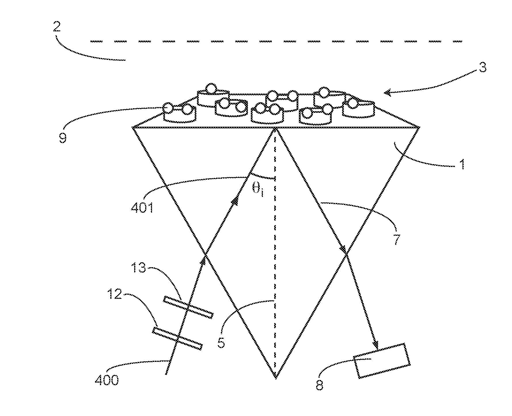
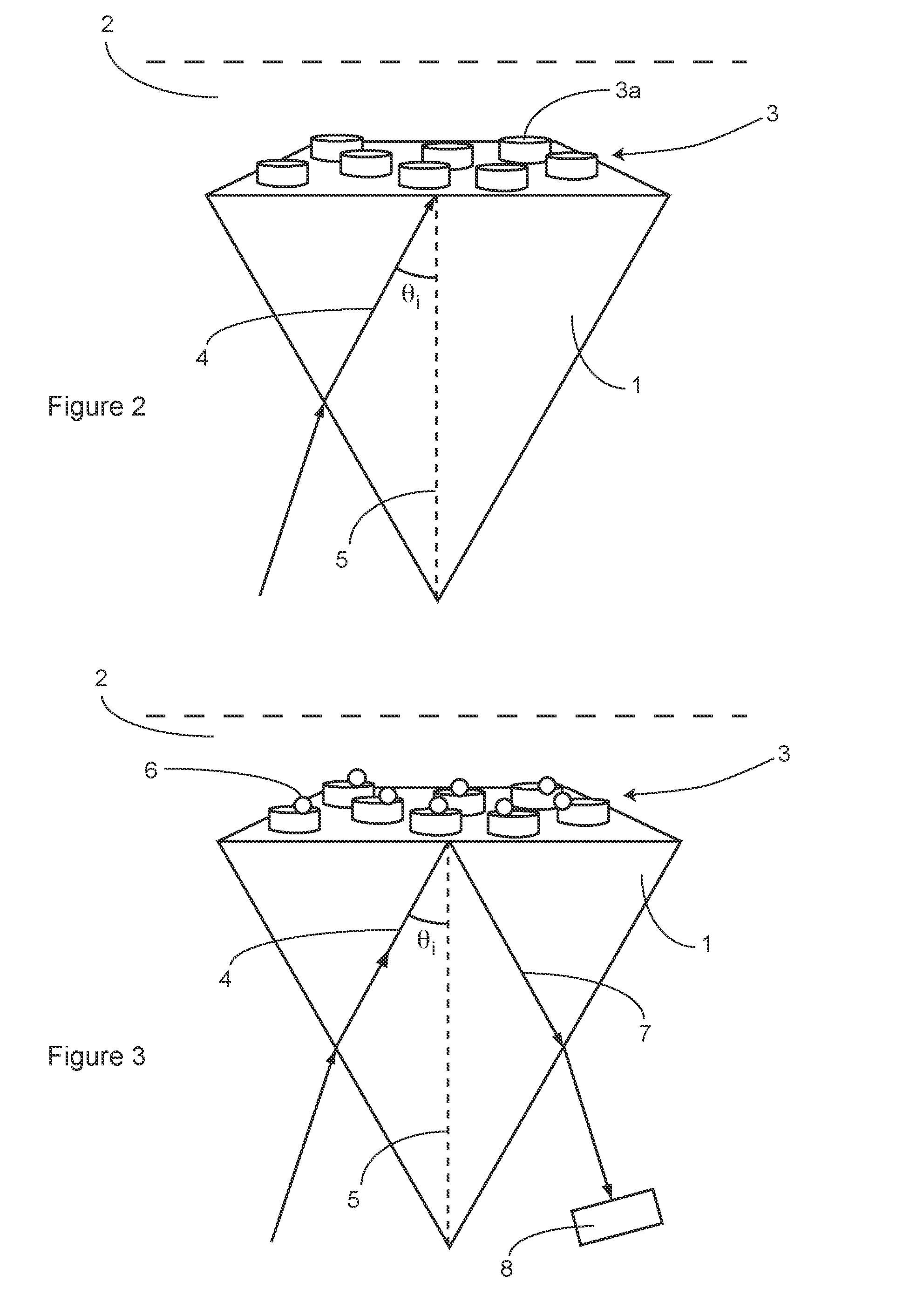
[0051]When a dielectric boundary with a plurality of small (in relation to the wavelength of the light) inclusions is illuminated above the critical angle, the collective coherent scattering of the inclusions interfere with the reflection from the boundary between the two media. At certain conditions, the components interfere completely destructively, and no light at all is reflected. And since the illumination takes place above the critical angle, no light is transmitted either. Instead, the incoming light is totally absorbed by the structure of small inclusions in the dielectric boundary.

[0052]In order to achieve total absorption in, the angle of the incident light to the boundary, θi, (i.e. in relation to the normal of the boundary) must fulfil the following relations:

[0053]For s-polarized light:

ωcρα(ω)=??+?cos??indicates text missing or illegible when filed

[0054]For p-polarized light:

ωcρα(ω)=-??+???,?indicates text missing or illegible when filed

[0055]where ω is the angular freq...


PUM


Abstract

The invention concerns a method for exciting a sub-wavelength inclusion structure, comprising: providing a first medium having a first refractive index ni and a second medium having a second refractive index nt, wherein ni>nt, wherein the sub-wavelength inclusion structure is arranged at a boundary between the first and second media, wherein the sub-wavelength inclusion structure exhibits polarizability properties; and directing light through the first medium towards the sub-wavelength inclusion structure. The angle of the incident light to the normal of the boundary, θi, is such that, for a given set of: frequency of the light; surface density of inclusions; average polarizability of the inclusion structure at the frequency; first refractive index; and second refractive index, θi fulfils at least one of the relations for s-polarized light and for p-polarized light described herein.

Description

TECHNICAL FIELD [0001]This invention relates to a method for exciting a sub-wavelength inclusion structure arranged at a boundary between a first and a second medium by directing light through the first medium towards the sub-wavelength inclusion structure. The invention also relates to a method for carrying out refractometric sensing, surface enhanced spectroscopy and / or optical trapping using the method for exciting the sub-wavelength inclusion structure.BACKGROUND OF THE INVENTION [0002]Nanotechnology and the use of nanostructured surfaces have greatly contributed to the development of new improved sensors. The nano-physical properties of the nanostructures, can greatly contribute to e.g. enhancing otherwise weak sensing signals or indirect sensing of changes in the sensing material or environment, as described in e.g. WO 2012 / 136440.[0003]One example is Surface Enhanced Raman Spectroscopy (SERS), described in e.g. US2012050732. SERS is an elaboration of Raman spectroscopy—a well...

Claims


Application Information

Patent Timeline
IPC IPC(8): G01N21/63G02B5/00G01N21/21G01N21/45G01N21/41G01N21/65
CPCG01N21/63G01N21/4133G01N21/658G01N21/211G01N21/45G02B5/008G01N21/554G01N21/648
Inventor KALL, MIKAELSVEDENDAHL, MIKAEL
Owner KALL MIKAEL
Why Eureka
Try Eureka