Reticulated open-cell foam modified by fibers extending across and between the cells of said foam and preparation methods thereof

a closed-cell foam and fiber technology, applied in the field of reticulated foam structures, can solve the problems of high back-pressure of fluid flowing through such materials to create the intended final product, inherently limited cell diameter range, and collapse of foam, and achieve the effect of increasing the volume of foam

Inactive Publication Date: 2014-11-06
EPIC VENTURES
View PDF5 Cites 8 Cited by
  • Summary
  • Abstract
  • Description
  • Claims
  • Application Information

AI Technical Summary

Benefits of technology

[0028]The incorporation of fibers into the foam modifies its effective porosity, increases the surface contact area and enhances its intrinsic mechanical support. The reticulated foam containing the fiber additives has utility in a number of applications such as for filtration, heat dissipation, or strong, lightweight mechanical structures. A fiber-enhanced reticulated polymer foam according to the invention is particularly useful as a template to fabricate fine-structure micro-porous reticulated foams made of metal, metal alloy, metal oxide, carbon-based or glass, some of which are particularly suited as battery electrodes.
[0037]In another embodiment of the invention an additive comprised of thin diameter, short fibers made from metal, metal alloy, metal oxides, glass, carbon or any polymer is incorporated into reticulated polymer foam, preferably reticulated polyurethane foam, subsequent to foam formation. The reticulated foam is first soaked in an organic solvent, such as chloroform, which solvent causes the foam to expand in all dimensions, increasing the volume of the foam by double or more. This process expands both the cell diameter and pore size (i.e. openings between adjacent cells). By adding one or more fiber additives of metal, metal alloy, metal oxides, polymer, carbon material or glass to the solvent, and dispersing such additive within the solvent, it is then possible to disperse the added fibers within the cells of the expanded reticulated polymer. The solvent is then evaporated, causing the foam to shrink back to its original size, leaving the fiber additive entrained and held within the reticulated foam cells.

Problems solved by technology

Prior art foamed materials consisting of non-polymer foam templates such as for example carbon or aluminum generally have limitations due to the high cost of producing such materials in commercial quantities, or having relatively small pore sizes between connecting cells, thereby creating high back-pressures for fluids flowing through such materials to create the intended final product.
Too much gas expansion causes “foam collapse”.
Although reticulated polyurethane foam is an excellent template for making metal, metal alloy, metal oxide, carbon and glass foamed constructs, the cell diameter range is inherently limited by the foam-formation and curing process, and is thereby not suitable for applications requiring pore sizes less than about 200 microns.
This process is limited to metals, and in final construct size, as it requires pressing the precursor material into pellets using a die, and firing in an inert atmosphere at high temperatures (i.e. 800° C.) to remove the carbon and nitrogen impurities.
The small pore size would also create a large back-pressure for some applications, e.g. use as filters, and would be difficult to use as a porous electrode since fluid infusion therein would be impractical.
Generally speaking, the prior art polymer foam-making techniques suffer broad dimensional limitations.
However, expanding the cells too much results in collapse of the foam structure.
Using such reticulated polymer foam structures as templates to produce foam structures made of other materials imposes inherent limitations on the surface area and pore size available in the so-formed reticulated foam, for example to catalyze chemical reactions or to act as a conductive matrix.

Method used


Image

  • Reticulated open-cell foam modified by fibers extending across and between the cells of said foam and preparation methods thereof
  • Reticulated open-cell foam modified by fibers extending across and between the cells of said foam and preparation methods thereof
  • Reticulated open-cell foam modified by fibers extending across and between the cells of said foam and preparation methods thereof

Examples


Embodiment Construction

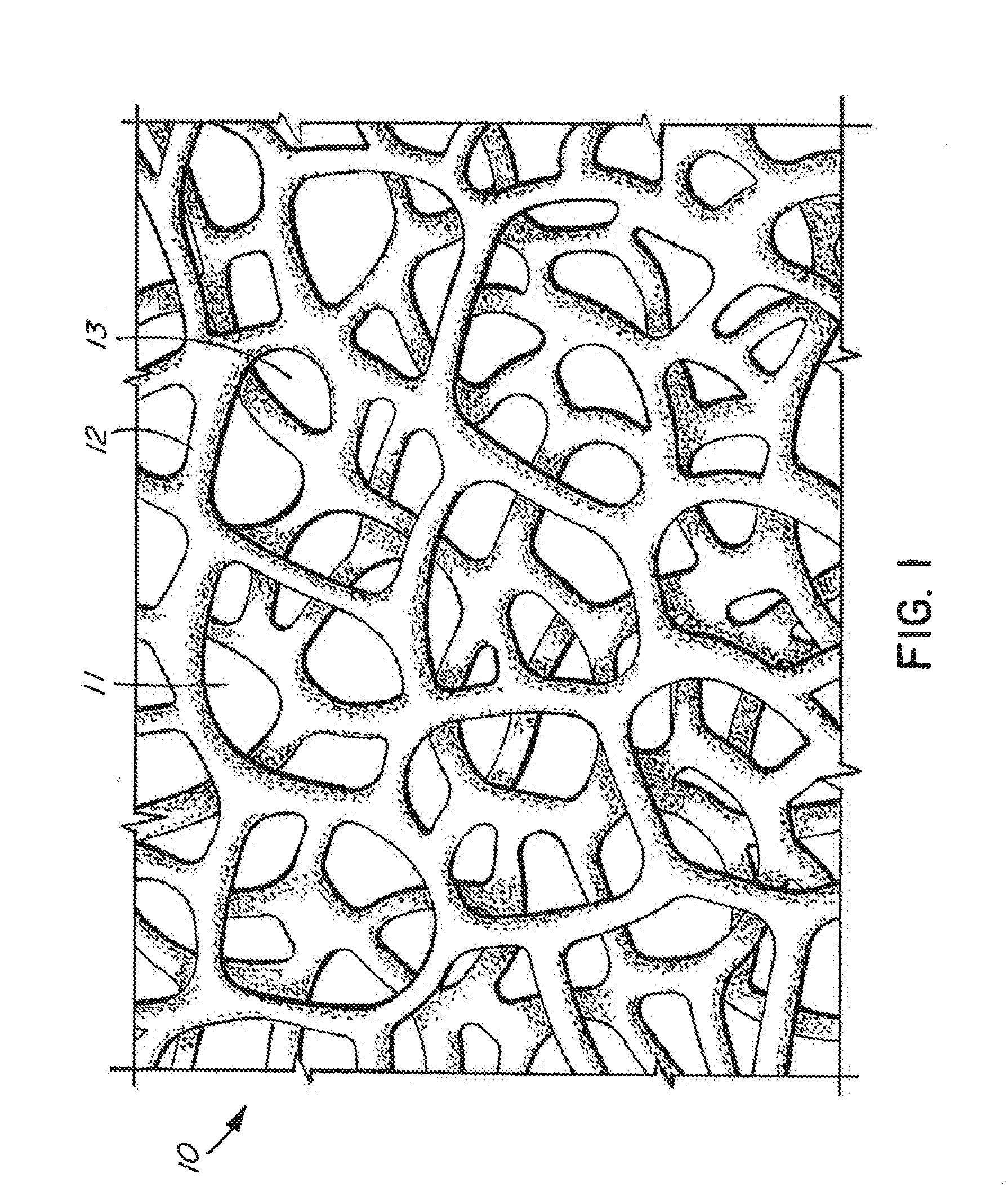
[0095]FIG. 1 is a three-dimensional sketch of commercially available reticulated polyurethane foam 10, having open cells 11 and ligaments or struts 12. Diameters of the open cells 11 can be in the range of 200 microns to 4 millimeters, which dimensions can be set by the production parameters. Pores 13 are in the range of 200 microns to about 3 millimeters across, which dimension is determined by the physical process of expanding bubbles during foam formation having common walls resulting from contact, which walls open, thereby forming a pore opening between adjacent cells.

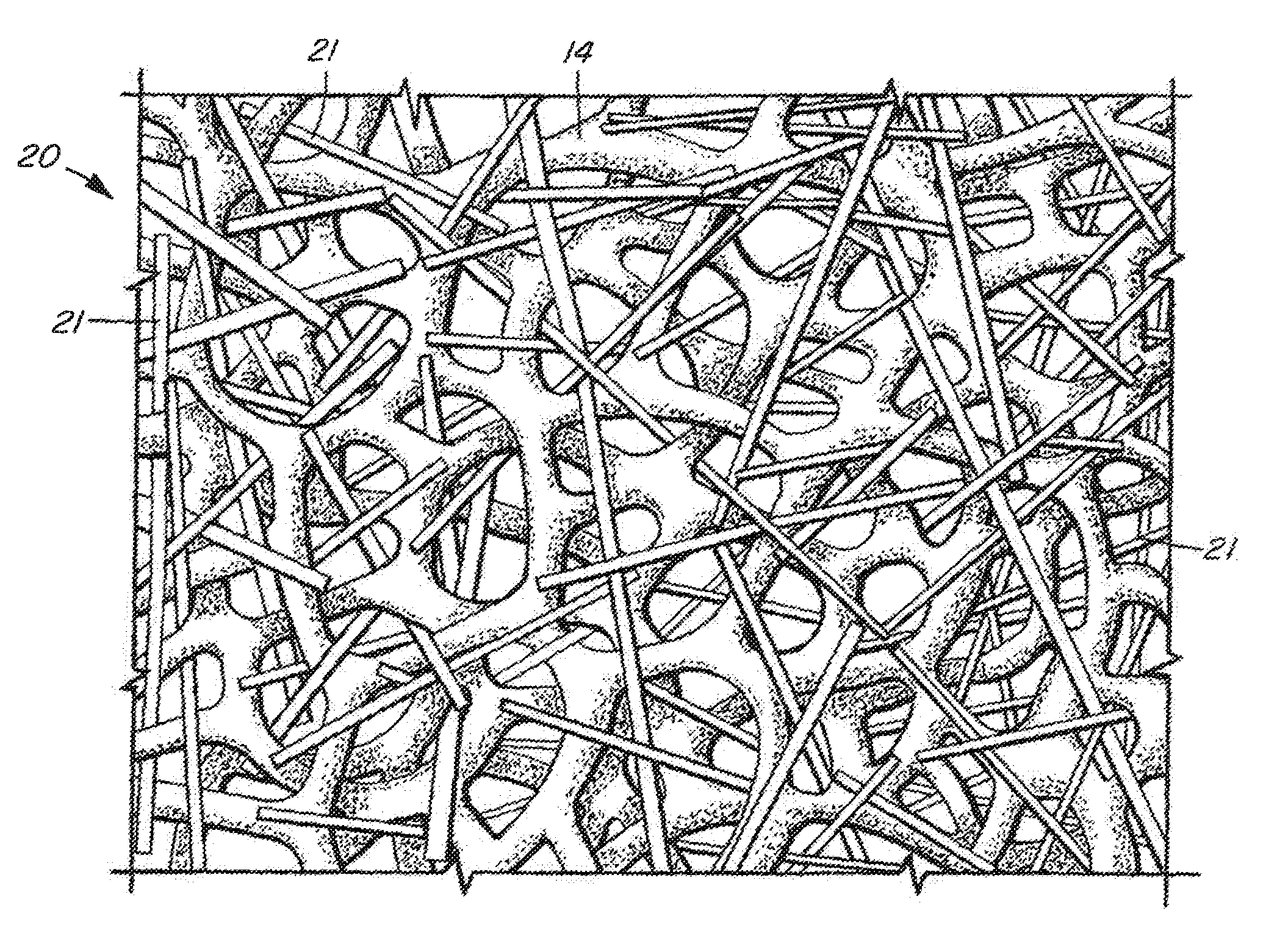
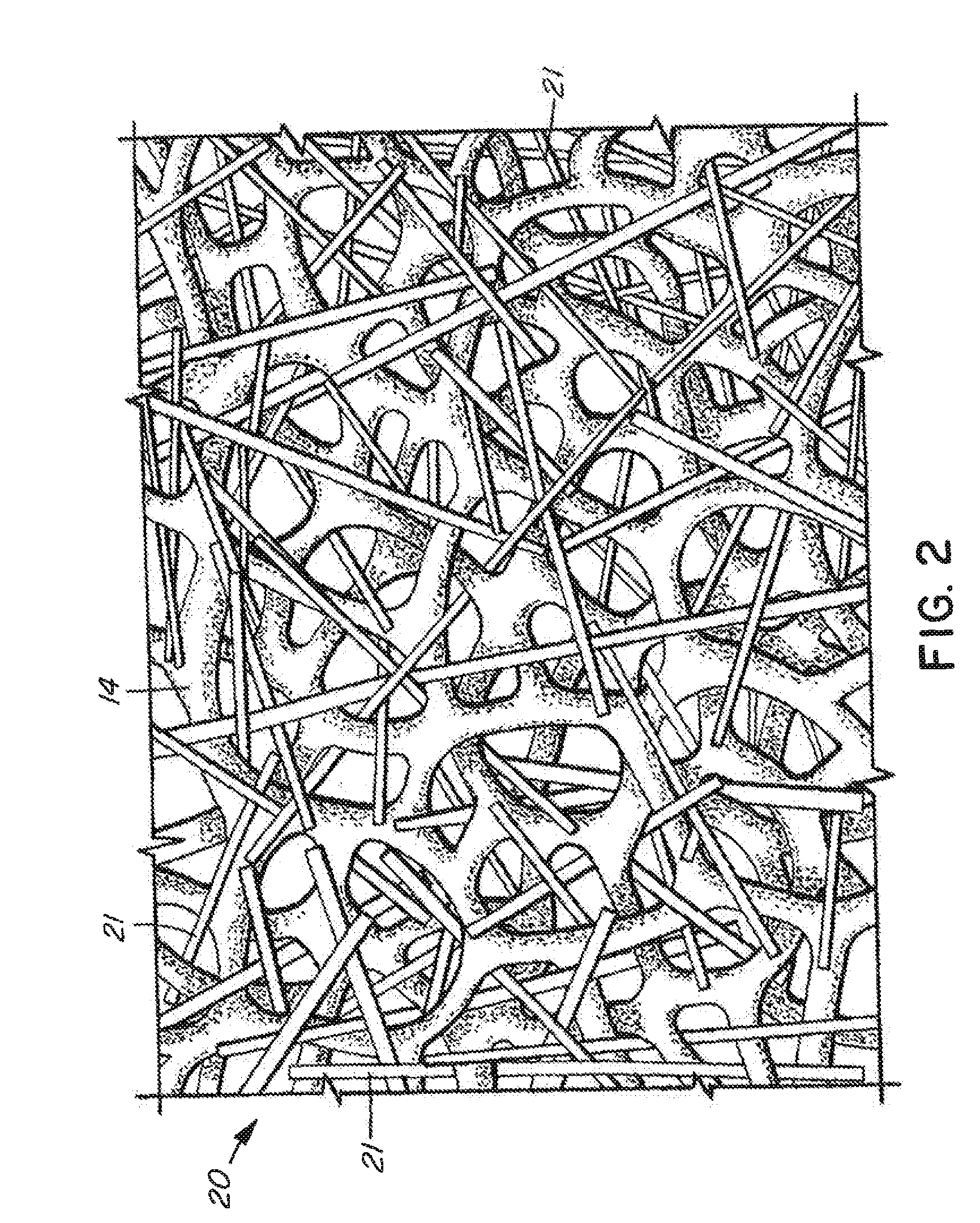
[0096]FIG. 2 illustrates a reticulated polyurethane foam 20 according to the preferred embodiment of the invention. The primary polymer foam structure characterized by ligaments 14 in FIG. 2 is preferably of the same dimensions as the finer-structured commercially producible prior art foams having cell diameters of about 200 microns to 4 millimeters (depending on the production process used to make the foam). In th...


PUM

PropertyMeasurementUnit
average lengthaaaaaaaaaa
pore sizesaaaaaaaaaa

Abstract

A reticulated foam structure comprising a plurality of closely-spaced fibers extending across and between the cells. A reticulated polymer foam structure is enhanced by fibers of metal, metal alloys, metal oxides, carbon or glass that are chopped or milled and introduced into the foam structure during foam formation or by entrainment of fibers into the foam. The resulting structure is used as a template to create a high porosity reticulated foam structure of a non-polymer material by coating the non-polymer onto the fiber-enhanced structure and removing the polymer by heating or pyrolizing. The design has utility for applications such as filtration, implants, heat transfer and electrodes, which require structures with low cost, high porosity, small effective pore sizes and large contact surface area.

Description

FIELD OF THE INVENTION[0001]The invention involves reticulated foam structures comprised of polymer, metal, metal alloys, metal oxides, carbon and glass, and the method for making such structures.BACKGROUND OF THE INVENTION[0002]Reticulated (or “open-cell”) foam is used in a variety of applications, including non-conductive applications such as filters, heat dissipation, rigid mechanical structures and catalysts, and conductive applications such as electrodes.[0003]Reticulated foam can be polymer-based or made of other materials such as carbon allotropes, metals, metal alloys, metal oxides and glass. Polymer-based reticulated foams can be made from polypropylene, polyurethane, polyethylene, polyester, polyether, acrylonitrile butadiene styrene, fluropolymers, polyvinyl chloride, cellulose, latex, etc., including co-polymers, such as ethylene vinyl acetate[0004]Reticulated polymer foams can also be used as templates to create foams made of other materials. For example, Inco Limited, ...

Claims


Application Information

Patent Timeline
Patent Type & Authority Applications(United States)
IPC IPC(8): C08J9/00C23C18/32
CPCC08J9/0085C23C18/32C08J2205/05C23C18/1641C23C18/1644C23C18/1657C23C18/1692Y10T428/249921
Inventor BERRANG, PETER G.
Owner EPIC VENTURES
Why Eureka
Try Eureka