Light deflector and laser light source including same

Inactive Publication Date: 2014-11-13
SHOWA OPTRONICS
View PDF3 Cites 2 Cited by
  • Summary
  • Abstract
  • Description
  • Claims
  • Application Information

AI Technical Summary

Benefits of technology

The present invention provides a light deflector that has a simple structure without movable parts and can correct the optical axis of a laser light source to achieve a stable output. A beam position detector is included to detect the position of a part of the fundamental wave and control the light deflector accordingly to reduce the amount of deviation. The light deflector can fine-adjust the deflection angle and can be operated without use of a high voltage, making it low-cost and suitable for incorporation into a laser light source.

Problems solved by technology

In a laser light source including mirrors for forming a laser resonator and minors for causing laser light to propagate properly by reflecting the laser light at appropriate points, when a distortion is generated in a housing, the distortion may cause a slight change in an angle of some mirror(s), and this may cause a deviation in the optical axis of laser light propagating inside the laser light source, which in turn may lead to a reduction in laser output and / or deterioration in laser beam quality.
Further, the deviation of the optical axis may also be caused by a stress applied to the laser light source from outside, such as when the laser light source set up at a certain location or incorporated into a laser application system is mounted on a distorted surface.
The distortion of the surface on which the laser light source is mounted may be caused even after the mounting of the laser light source due to a change in the environment temperature or due to the heat generated from the laser application system into which the laser light source is incorporated.
However, in a case where the purpose of use is limited to adjustment of an optical axis of a laser light source, the time responsiveness and / or the range of deflection angle provided by the light deflectors used in the foregoing systems may be beyond what is required.
Further, in a case where the light deflectors of the foregoing prior art systems are used in adjustment of an optical axis of a laser light source, there may be problems such as that the light deflectors requiring a high voltage and / or high frequency tend to result in a higher cost, and that the light deflectors using a motor, which is a movable part, can adversely affect the laser characteristics during an operation of the laser light source and / or are inappropriate for incorporation into a laser light source in which outgassing likely creates a problem.
Further, the prior art light deflectors are large in size and high in cost.

Method used


Image

  • Light deflector and laser light source including same
  • Light deflector and laser light source including same
  • Light deflector and laser light source including same

Examples


Embodiment Construction

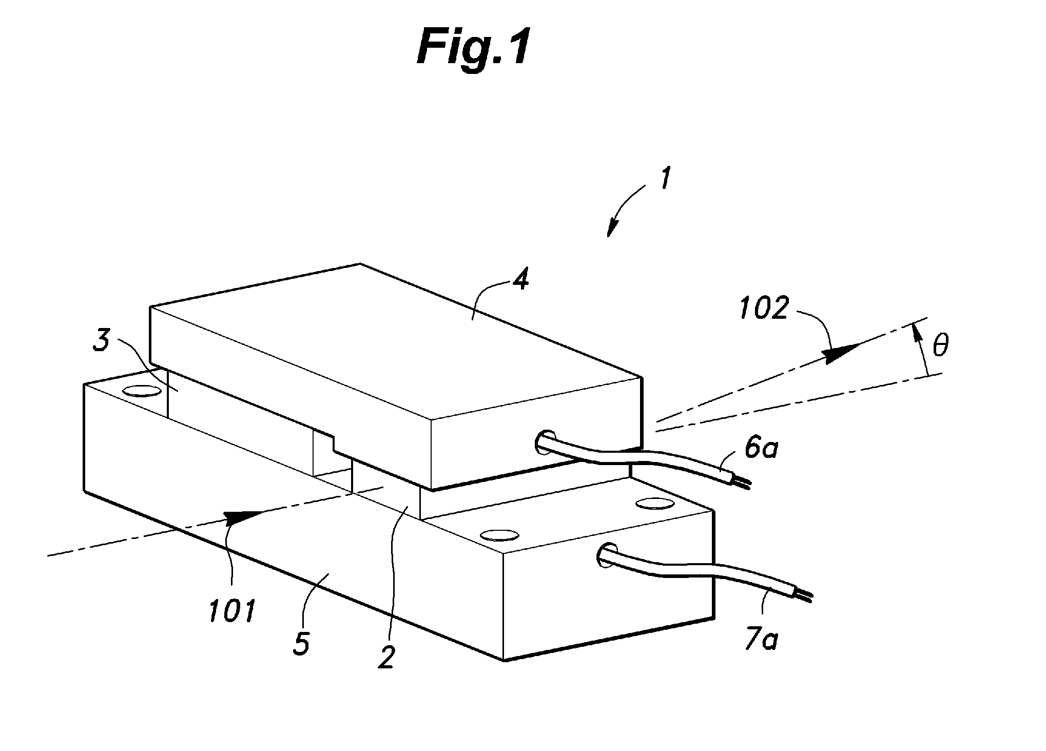
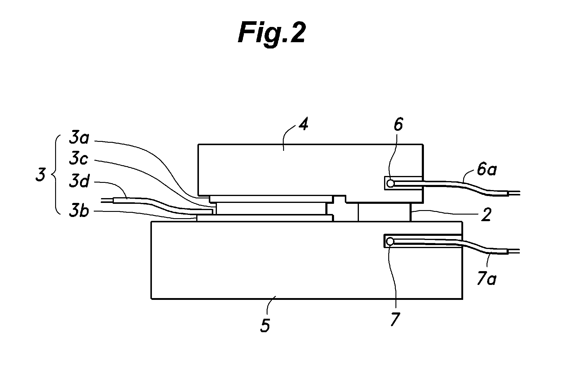
[0027]FIG. 1 is a perspective view of a light deflector 1 according to an embodiment of the present invention, and FIG. 2 is a cross-sectional view of the light deflector 1 shown in FIG. 1. The deflector 1 includes a transparent medium 2 and an electronic cooling element (thermo-electric cooler) 3 which are arranged next to each other and interposed between a first metallic piece 4 and a second metallic piece 5 each made of brass. The first metallic piece 4 has a first temperature sensor 6 embedded therein and the second metallic piece 5 has a second temperature sensor 7 embedded therein to monitor the temperature. Each of the first temperature sensor 6 and the second temperature sensor 7 is embodied as a thermistor having an electric resistance that varies with temperature. The light deflector 1, excluding electrodes 3d of the electronic cooling element 3 and electrodes 6a and 7a of the temperature sensors 6 and 7, has a dimension of 30 mm×10 mm×10 mm.

[0028]The transparent medium 2...


PUM


Abstract

A light deflector for deflecting a propagation direction of laser includes: a first metallic piece and a second metallic piece spaced apart from each other; and a transparent medium and an electronic cooling element disposed between the first metallic piece and the second metallic piece such that each of the transparent medium and the electronic cooling element is in contact with the first metallic piece and the second metallic piece. The electronic cooling element creates a temperature difference between the first metallic piece and the second metallic piece to vary a refractive index of the transparent medium.

Description

TECHNICAL FIELD[0001]The present invention relates to a light deflector that does not include a mechanically movable part and does not require a high voltage for operation, and a laser light source using the light deflector for correcting a deviation of the optical axis.BACKGROUND OF THE INVENTION[0002]In a laser light source including mirrors for forming a laser resonator and minors for causing laser light to propagate properly by reflecting the laser light at appropriate points, when a distortion is generated in a housing, the distortion may cause a slight change in an angle of some mirror(s), and this may cause a deviation in the optical axis of laser light propagating inside the laser light source, which in turn may lead to a reduction in laser output and / or deterioration in laser beam quality.[0003]This deviation of the optical axis may be caused by a change in the housing temperature due to heat generated by the laser light source itself or a change in the environment temperat...

Claims


Application Information

Patent Timeline
IPC IPC(8): H01S3/13H01S3/00G02F1/29
CPCH01S3/1305G02F1/29H01S3/13H01S3/0092H01S3/0071G02F1/0147G02F1/295G02F1/37G02F2201/58G02F2203/24H01S3/1306H01S3/109H01S3/083
Inventor KADOYA, MINORU
Owner SHOWA OPTRONICS
Why Eureka
Try Eureka