Charged particle vortex wave generation

Active Publication Date: 2014-11-27
UNIVERSITY OF ANTWERP
View PDF2 Cites 10 Cited by
  • Summary
  • Abstract
  • Description
  • Claims
  • Application Information

AI Technical Summary

Benefits of technology

[0009]It is an object of the present invention to provide good and

Problems solved by technology

However, precise control over thickness and orientation limits the range of applications in which EMCD can be used.
EMCD is furthermore fundamentally limited to a spatial resolution bigger than a few unit cells, e.g. 2 nm, because elastic diffraction is essential in creating the signal.
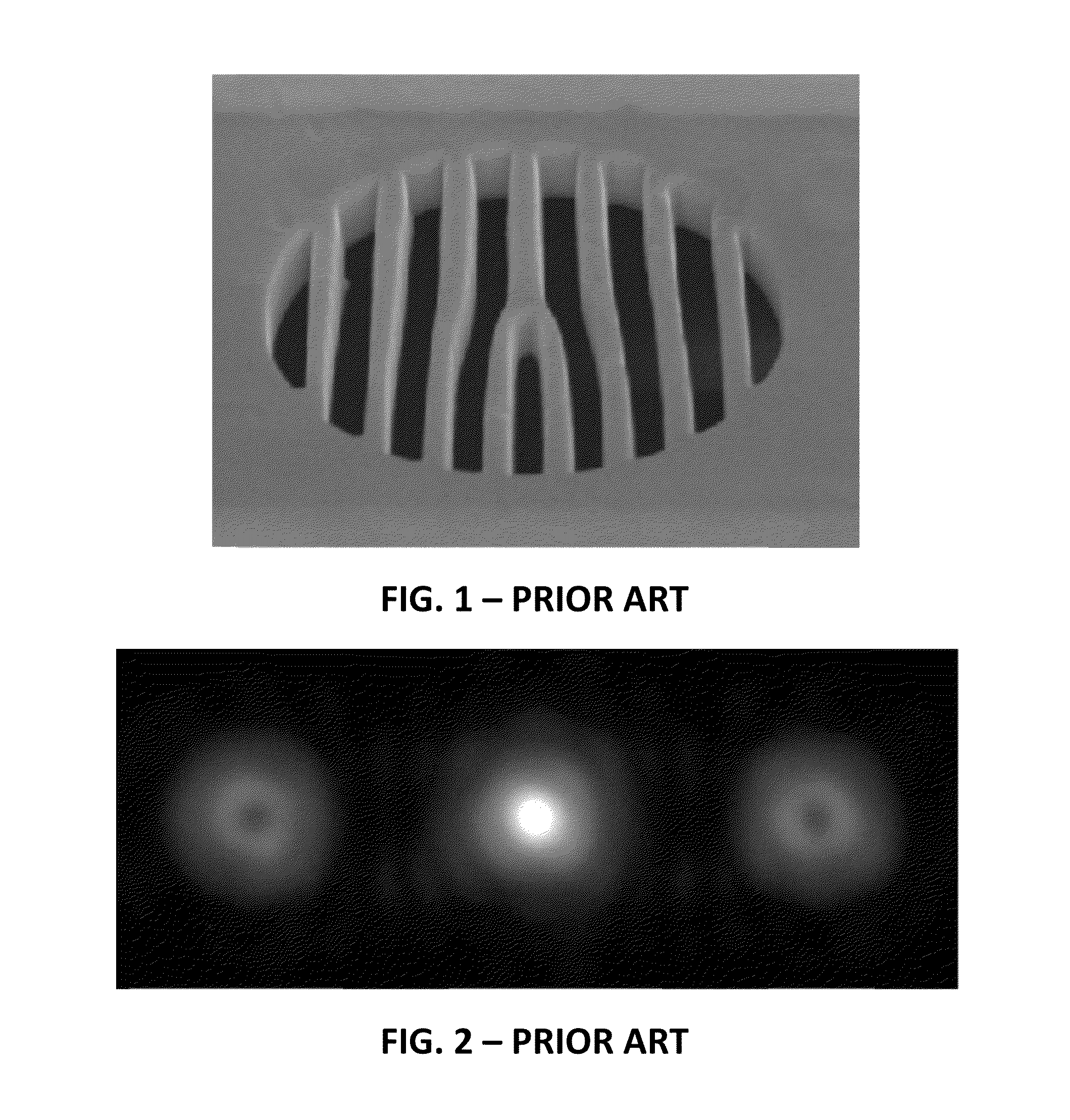
However, this method has the disadvantage that the grating simultaneously produces three output beams, as shown by the electron intensity as obtained from such grating in the far field depicted in FIG. 2: the vortex wave of interest, the reference beam and the complex conjugate

Method used


Image

  • Charged particle vortex wave generation
  • Charged particle vortex wave generation
  • Charged particle vortex wave generation

Examples


Embodiment Construction

[0049]The present invention will be described with respect to particular embodiments and with reference to certain drawings but the invention is not limited thereto but only by the claims. The drawings described are only schematic and are non-limiting. In the drawings, the size of some of the elements may be exaggerated and not drawn to scale for illustrative purposes. The dimensions and the relative dimensions do not correspond to actual reductions to practice of the invention.

[0050]Furthermore, the terms first, second and the like in the description and in the claims, are used for distinguishing between similar elements and not necessarily for describing a sequence, either temporally, spatially, in ranking or in any other manner. It is to be understood that the terms so used are interchangeable under appropriate circumstances and that the embodiments of the invention described herein are capable of operation in other sequences than described or illustrated herein.

[0051]Moreover, t...


PUM


Abstract

A device for imparting an orbital angular momentum to a charged particle wave propagating along a beam axis in a charged particle beam generating apparatus is described. The device comprises a support element having a target region adapted for transmitting a charged particle wave propagating along a beam axis and an induction means for inducing a magnetic flux along an elongated profile having a free end portion located in the target region and the induction means is adapted for providing a magnetic flux in the elongated profile in order to induce an angular gradient, relative to the beam axis, of the phase of the charged particle wave when transmitted through the target region. A corresponding method is also disclosed, as well as the use thereof in electron microscopy.

Description

FIELD OF THE INVENTION[0001]The invention relates to the field of charged particle beam manipulation. More specifically it relates to methods and systems for imparting an orbital angular momentum to a charged particle beam, e.g. an electron beam or ion beam.BACKGROUND OF THE INVENTION[0002]Most wave phenomena encountered in physics textbooks consider planar or spherical waves, which both have in common that their wavefronts form separated planes in space. However, waves of different topology can theoretically exist. An interesting class of such waves are so-called vortex waves, which are also known as waves with a topological charge or waves with a phase singularity.[0003]Vortex waves were first discovered in radio waves and later found many applications in light optics. Such waves carry an orbital angular momentum (OAM) of m h per primary particle, in which the topical charge m is a non-zero integer, e.g. +1 or −1. The orbital angular momentum depends on the spatial distribution of...

Claims


Application Information

Patent Timeline
IPC IPC(8): H01J37/04H01J37/26
CPCH01J37/261H01J37/04H01J3/02H01J3/021H01J37/06H01J37/08H01J37/256H01J2237/06383H01J2237/2614H01J37/26
Inventor VERBEECK, JOHANVAN TENDELOO, GUSTAAF
Owner UNIVERSITY OF ANTWERP
Why Eureka
Try Eureka