Toner housing container and image forming apparatus

Active Publication Date: 2014-11-27
RICOH KK
View PDF2 Cites 24 Cited by
  • Summary
  • Abstract
  • Description
  • Claims
  • Application Information

AI Technical Summary

Benefits of technology

[0020]The present invention can provide a toner housing container that can solve the convention

Problems solved by technology

However, when a shutter member is used in a system that employs the mechanism of uplifting the toner by the uplifting portion and supplying the toner into the conveying pipe, the conveying

Method used


Image

  • Toner housing container and image forming apparatus
  • Toner housing container and image forming apparatus
  • Toner housing container and image forming apparatus

Examples


production example 1

Production of Crystalline Polyester Resin 1

[0292]A reaction tank equipped with a cooling pipe, a stirrer, and a nitrogen introducing pipe was charged with sebacic acid (202 parts) (1.00 mol), 1,6-hexanediol (154 parts) (1.30 mol), and tetrabutoxy titanate as a condensation catalyst (0.5 parts), and they were reacted under nitrogen stream at 180° C. for 8 hours while distilling away water to be produced. Next, while raising the temperature gradually to 220° C., they were reacted under nitrogen stream for 4 hours while distilling away water to be produced and 1,6-hexanediol, and further reacted at reduced pressure of from 5 mmHg to 20 mmHg until Mw reached about 15,000, to thereby obtain [Crystalline Polyester Resin 1]. The obtained [Crystalline Polyester Resin 1] had Mw of 14,000, and a melting point of 66° C.

production example 2

Production of Non-Crystalline Polyester Resin 1 (Unmodified Polyester Resin)

[0293]A reaction tank equipped with a cooling pipe, a stirrer, and a nitrogen introducing pipe was charged with bisphenol A-EO 2 mol adduct (222 parts), bisphenol A-PO 2 mol adduct (129 parts), terephthalic acid (150 parts), adipic acid (15 parts), and tetrabutoxy titanate (0.5 parts), and they were reacted under nitrogen stream at 230° C. at normal pressure for 8 hours while distilling away water to be produced. Next, they were reacted at reduced pressure of from 5 mmHg to 20 mmHg, and cooled to 180° C. when the acid value became 2 mgKOH / g. Trimellitic anhydride (35 parts) was added thereto, and they were reacted at normal pressure for 3 hours, to thereby obtain [Non-Crystalline Polyester Resin 1]. The obtained [Non-Crystalline Polyester Resin 1] had Mw of 6,000 and Tg of 54° C.

production example 3

Production of Polyester Prepolymer

[0294]A reaction tank equipped with a cooling pipe, a stirrer, and a nitrogen introducing pipe was charged with bisphenol A-EO 2 mol adduct (720 parts), bisphenol A-PO 2 mol adduct (90 parts), terephthalic acid (290 parts), and tetrabutoxy titanate (1 part), and they were reacted under nitrogen stream at 230° C. at normal pressure for 8 hours while distilling away water to be produced. Next, they were reacted at reduced pressure of from 10 mmHg to 15 mmHg for 7 hours, to thereby obtain [Intermediate Polyester 1]. [Intermediate Polyester 1] had Mn of 3,200 and Mw of 9,300.

[0295]Next, a reaction tank equipped with a cooling pipe, a stirrer, and a nitrogen introducing pipe was charged with the obtained [Intermediate Polyester 1] (400 parts), isophorone diisocyanate (95 parts), and ethyl acetate (500 parts), and they were reacted under nitrogen stream at 80° C. for 8 hours, to thereby obtain a 50% ethyl acetate solution of [Polyester Prepolymer 1] havin...


PUM


Abstract

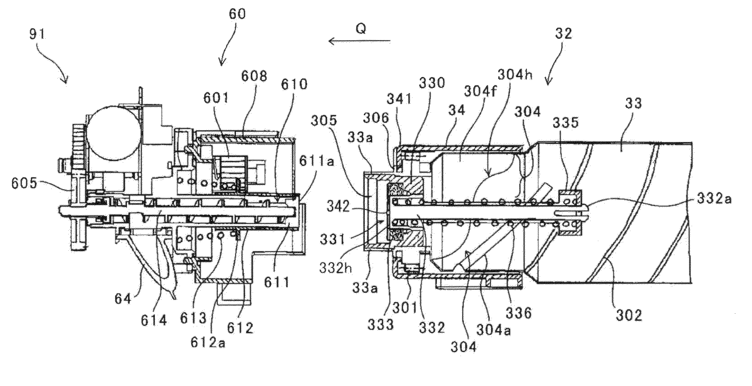
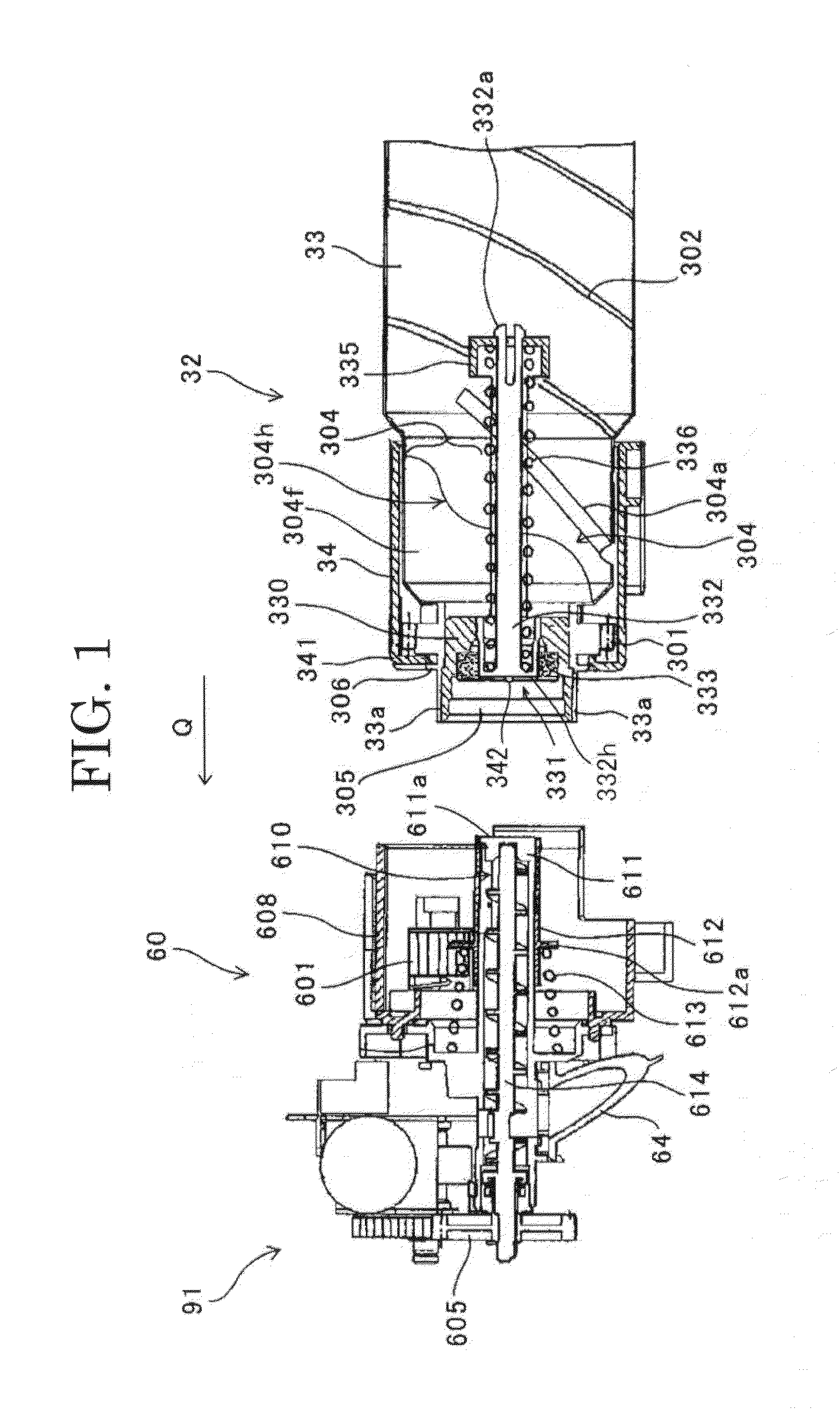
A toner housing container includes: container body; conveying portion; pipe receiving port; and uplifting portion. Container body includes; protruding portion protruding from container body interior side of container opening portion to one end of container body; and shutter member moving between closing and opening positions to close and open container opening portion. Uplifting portion includes: uplifting wall surface extending from container body internal wall surface toward protruding portion; and curving portion curving to conform to protruding portion. Shutter member moves from closing to opening position upon push by conveying pipe. When toner housing container is mounted on toner conveying device, protruding portion is present between curving portion and toner receiving port of conveying pipe inserted and extends along shutter member moving region. Toner has bulk density of ≦0.399 g/cm3 when toner housing container is shaken up-and-down 10 times at 25° C., 50% RH, and put such that container opening portion faces downward.

Description

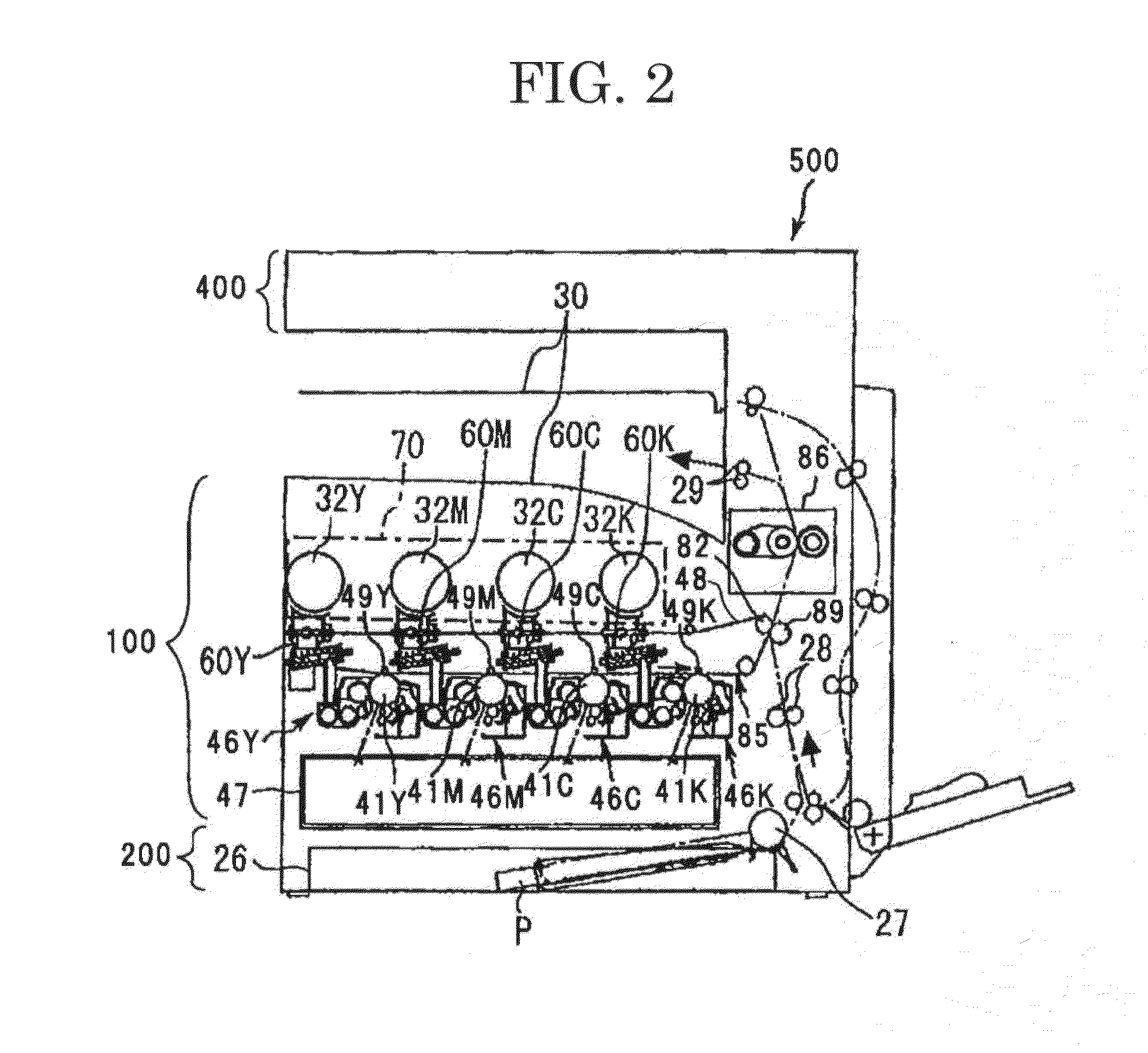
BACKGROUND OF THE INVENTION[0001]1. Field of the Invention[0002]The present invention relates to a toner housing container and an image forming apparatus.[0003]2. Description of the Related Art[0004]In electrophotographic image forming apparatuses, a powder conveying device supplies (or replenishes) a toner serving as a developer from a toner container, which is a powder housing container housing the developer in the powder form, into a developing device.[0005]For example, there is proposed a toner housing container that includes a rotatable tubular powder housing member, a conveying pipe receiving member fixed to the powder housing member, an opening provided in the conveying pipe receiving member, and an uplifting portion configured to uplift the toner upward in the container along with rotation of the container body (e.g., see Japanese Patent Application Laid-Open (JP-A) No. 2012-133349). According to this proposed technique, the toner is uplifted by the uplifting portion along w...

Claims


Application Information

Patent Timeline
IPC IPC(8): G03G15/08
CPCG03G15/0865G03G9/0821G03G15/0872G03G15/0886
Inventor YAMABE, JUNJITERAZAWA, SEIJITAMAKI, SHINJIKIKUCHI, KENJIHOSOKAWA, HIROSHIKATOH, SHUNJITERANISHI, RYOICHIIKEGUCHI, HIROSHISUZUKI, MICHIHARU
Owner RICOH KK
Why Eureka
Try Eureka