Wrist Worn Device with Inverted F Antenna

a technology of inverted f antenna and wristband, which is applied in the field of wireless communication, can solve the problems of difficult to design an efficient antenna constraint to a relatively low volume, and increase the complexity of the antenna design, and achieve the effect of less flexibility

Inactive Publication Date: 2014-12-04
KATZ DANIEL A
View PDF13 Cites 113 Cited by
  • Summary
  • Abstract
  • Description
  • Claims
  • Application Information

AI Technical Summary

Benefits of technology

[0042]This antenna, according to the present invention, obtains a basic F-inverted topology, i.e. feeding leg and shorting (grounding) leg perpendicularly connected to the main radiating element, however this element, according to the present invention and differently from present art IFA (Inverted F Antenna), is not a straight line but forming a bent line, and not on the antenna ground plane but on a plane parallel to the ground plane; further according to the present invention and differently from present art PIFA (Planar Inverted F Antenna), the radiating element is a “wire”, i.e. a conductor shaped with a considerable length but small width and small height (such as a typical copper wire or trace on a PCB), and typically not with large area, so not considered a planar antenna. Furthermore, according to the present invention, the radiating wire is bent substantially following the perimeter of the ground plane below it, so placed on the edge or out border of the device, hence less disturbing or being disturbed by a display placed on the middle of said ground plane.
[0043]As a person skilled in the art may appreciate, the distance between the feeding leg and the shorting leg, which are substantially parallel to each other, could be adjusted to optimize the matching, i.e. minimize the return loss at a specific frequency. Typically, with a rectangular ground plane of 40×50 mm, or a round ground plane with 50 mm in diameter, a distance of 10 mm between feeding leg and shorting leg provided good matching of −20 dB return loss or better, at a resonance frequency of 406 MHz, obtaining about 3% bandwidth (between −10 dB points). Typically at these conditions, the radiating wire was placed about 15 mm above ground plane, and its length was more or less similar to the ground plane circumference, i.e. 15-20 cm, more or less a quarter wavelength at 406 MHz.
[0046]Furthermore, according to the present invention, the radiating wire might overlap itself near said gap, which is quite uncommon in inverted F antenna present art. Such feature provides an additional tool to adjust the resonance frequency of the antenna according to the present invention, even when there is less flexibility in varying the ground plane dimensions.
[0047]Further, according to the present invention, it is possible to configure the radiating wire to change its distance from said ground plane, obtaining at least two positions: (a) stowed position, where the radiating wire is close to the ground plane; (b) deployed position, where the distance between the ground plane and the radiating wire plane is larger. Preferably, both feeding leg and shorting leg can be made of elastic conductors, which collapse in the stowed position but strictly erected in the deployed position. When deployed, the radiating wire can be supported by a non conductive structure, such as two or three plastic shafts.
[0063]g. Adjusting the distance between said first point and said second point to minimize reflection;

Problems solved by technology

As a person skilled in the art may appreciate, it is not easy to design an efficient antenna constraint to a relatively low volume.
This required coexistence of antenna and display presents additional complexity to the antenna design, as the display is both disturbing to and disturbed by the antenna, in terms of both mechanical design and electrical performance.

Method used


Image

  • Wrist Worn Device with Inverted F Antenna
  • Wrist Worn Device with Inverted F Antenna
  • Wrist Worn Device with Inverted F Antenna

Examples


second embodiment

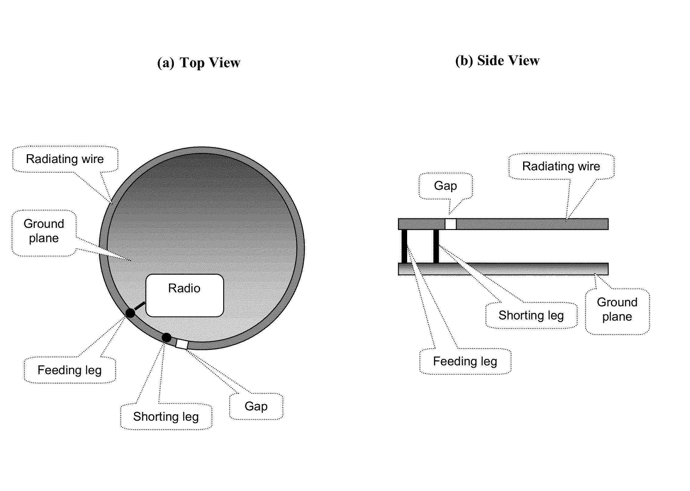
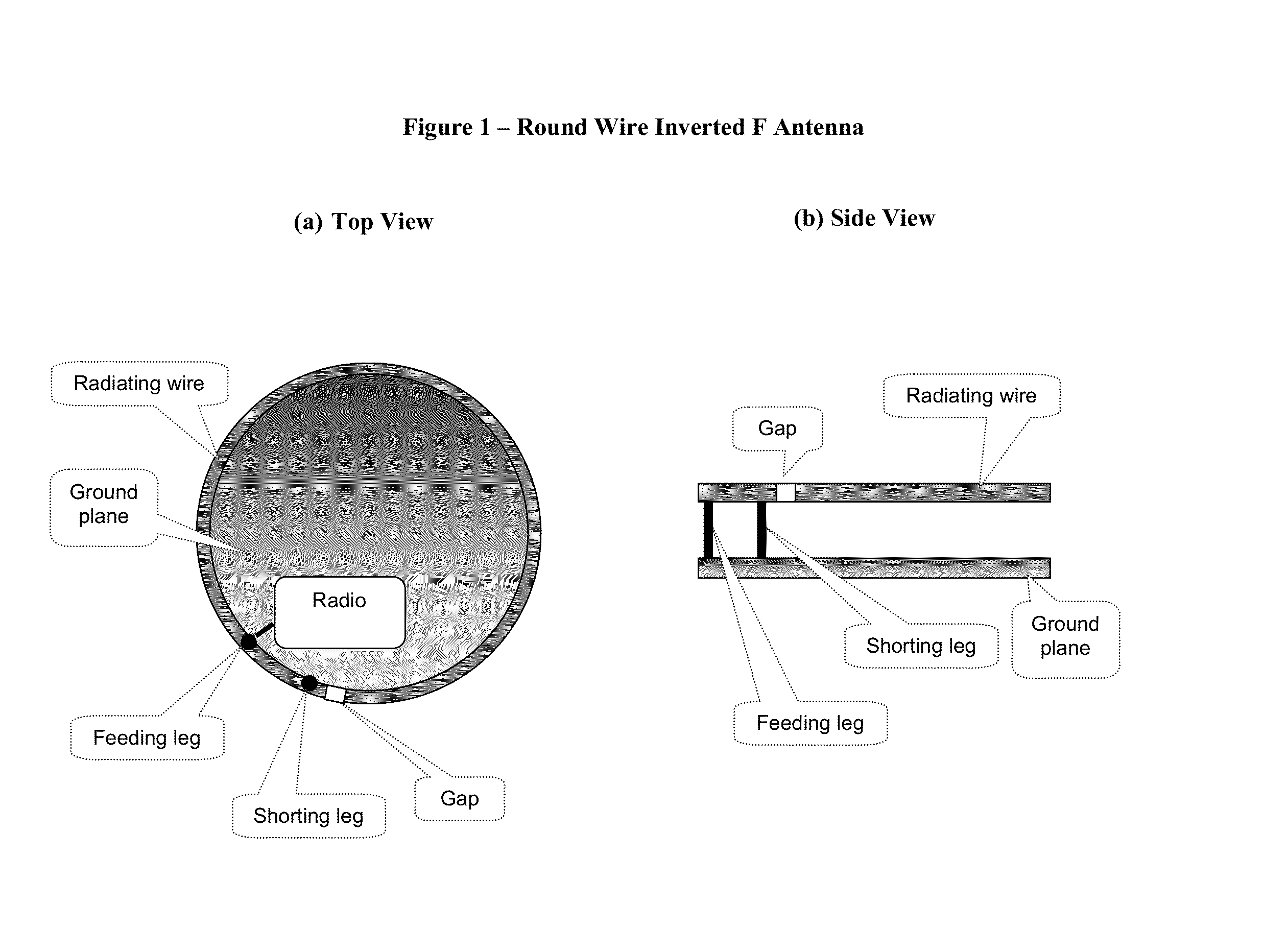
[0090]According to the present invention, the radio is a GNSS (Global Navigation Satellite System) receiver, e.g. the US GPS or Russian GLONASS or European Galileo, but particularly compatible with the US Global Positioning System (GPS). Then, the antenna is configured to the 1575 MHz band, where a quarter wave length is equal to about 5 cm. In this case, the ground plane can be configured to a circumference of about 5 cm, or larger and then the radiating wire would probably not cover all that circumference but obtain a relatively large gap between its ends.

[0091]Further according to a preferred embodiment of the present invention, the communication device is configured to be worn on a human body, particularly on the wrist, wherein the ground plane configured between the human body and the radiating wire.

[0092]FIG. 5 illustrates a Wrist Worn Communication Device according to the present invention. The device is shown worn on a human wrist, in (a) top view and (b) side view. It can b...

fourth embodiment

[0098]FIG. 9 illustrates a Wrist Worn Communication Device In background of Satellite System, according to said fourth embodiment of the present invention. A human hand is depicted, with a communication device, shown in (cut section) side view mounted on the wrist. The side view of the communication device shows a radiating wire placed in parallel and over a ground plane (ground plane close to wrist), with a feeding leg and shorting leg perpendicular to the ground plane. Also, a display and a GPS antenna are shown on the ground plane. GPS satellites are illustrated on the upper part of the figure, broadcasting signals apparently arriving to the GPS antenna, while the radiating wire on top of the communication device is shown transmitting a signal arriving at the illustrated SAR satellite on the upper part of the picture.

[0099]According to said fourth embodiment of the present invention, the communication device additionally comprises a temperature sensor, and a barometric pressure s...


PUM


Abstract

The present invention discloses a wrist worn communication device, possibly integrated with a wrist watch, comprising a radio coupled to a low profile antenna. The antenna, obtaining low and medium angle elevation radiation enabling efficient satellite communications, is configured on the perimeter of the device, giving room for a display on top of this compact device. Preferably, the display is configured to indicate the time, but also possibly other parameters such as position, speed, altitude, temperature, air pressure, heart pace, messages, alarms and so on. According to a preferred embodiment of the present invention, said device is a Personal Locator Beacon (PLB) configured to broadcast distress signals detectable by satellites. According to another embodiment of the present invention, said radio is a GPS receiver.

Description

BACKGROUND OF THE INVENTION[0001]The present invention relates to wireless communications and particularly to Radio Wave Antennas.[0002]Efficiency of a transmitting antenna is usually defined as the ratio between the power the antenna radiates and the power put into the antenna by a coupled transmitter (or mirrored equivalently for receiving). Obviously, a high efficiency is usually desirable in an antenna.[0003]The physical size of an antenna, normalized to its operating wavelength, usually refers in the art as the “electrical size” of the antenna, so a “small antenna” usually (including in the present document) means an Electrically Small Antenna (ESA). Clearly, small antennas are desirable, particularly in mobile and portable devices.[0004]Ideally, a small and efficient antenna would be usually chosen, however, a well known rule trades off between the antenna physical size and its electrical efficiency, limiting the miniaturization of the electrical size of an antenna, for a give...

Claims


Application Information

Patent Timeline
Patent Type & Authority Applications(United States)
IPC IPC(8): H01Q1/27
CPCH01Q1/273H01Q9/42
Inventor KATZ, DANIEL A.
Owner KATZ DANIEL A
Why Eureka
Try Eureka