Normal-incidence broadband spectroscopic polarimeter containing reference beam and optical measurement system

Active Publication Date: 2014-12-04
BEI OPTICS TECHNOLOGY COMPANY LIMITED
View PDF0 Cites 15 Cited by
  • Summary
  • Abstract
  • Description
  • Claims
  • Application Information

AI Technical Summary

Benefits of technology

The invention is a special device called a "normal-incidence broadband spectroscopic polarimeter containing reference beam." This device has several technical benefits. First, it is easy to adjust the focus, meaning it can clearly image light beams. Second, it does not cause any color distortion when it splits light beams. Third, it maintains the polarization characteristics of the light beams, which helps to keep them in the correct state. Fourth, it has very good light transmission efficiency, which means it can capture and transmit light very well. Fifth, it is easier to use than previous devices. These features make this device a great choice for optical measurement systems.

Problems solved by technology

There are some issues in the first focusing method in this case: lens usually has chromatic aberration which results in different wavelengths of light focusing on different locations, increasing the error and thus reducing the measurement accuracy.
It is also hard to find the lens materials with good transmission in the whole broadband wavelength range.
Those skilled in the art can clearly understand that the entire optical system is adjusted by the second focusing method, and it is very difficult to achieve precise measurement due to the requirements and limits on the weight and speed of the system.
Although the application of curved mirror does not produce chromatic aberration and thus improve the focusing and measurement accuracy, compared with lens, it is more difficult to align the optical path with curved mirror.
For example, (1) elliptical mirror: While the spatial location of two focus points is relatively fixed, the adjustable range of optical path and focusing position is very limited by adjusting the individual elliptical mirror after the incident light path was corrected.
(2) Toroidal mirror: Although the two corresponding focus points can be achieved in a certain range of incident angles, the spatial relationship of the two focus points changes with the relationship between incident light and toroidal mirror, and the correlations between two focus points are complex and it is very difficult to achieve focusing.
Another drawback is that its adjustable range is small and is easy to create image aberrations.
(3) Off-axis parabolic mirror: The adjustable range is very limited because the aberrations were resulted as the angle of off-axis parabolic mirror change relative to the direction of incident light.
While a wide range of the focusing position can be achieved by moving the off-axis parabolic mirror along the direction of the collimated light beam, the relative position of focus point to the off-axis parabolic mirror centre cannot be changed.
This also limits the adjustable range of the focus points.
In summary, the use of a single curved mirror itself does not produce chromatic aberration, but it is difficult to adjust and control the direction of the optical path and focusing positions by simple adjustment.
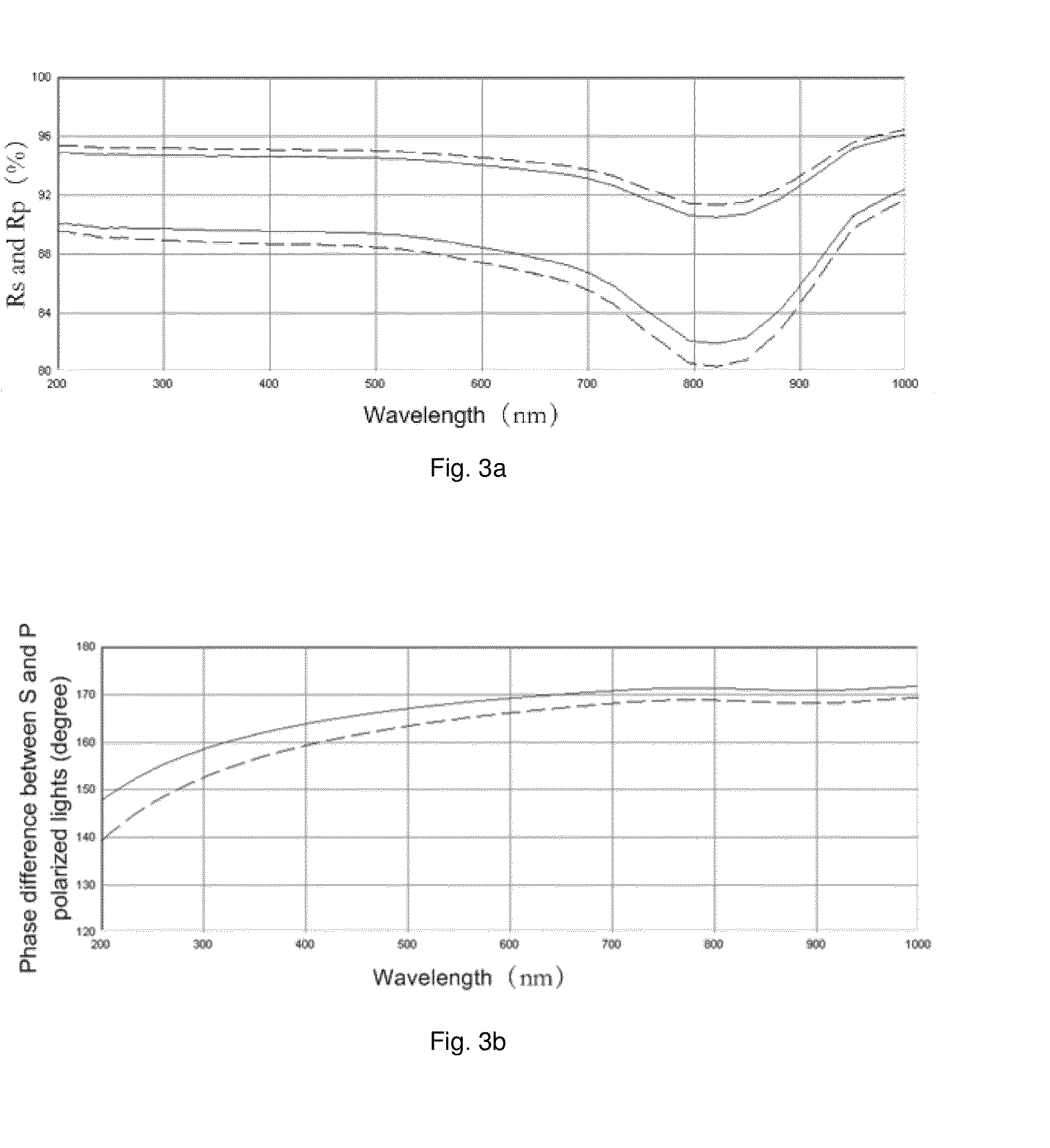
In short, because the polarization states S and P with the polarization direction orthogonal to each other have different reflectivity and phase change, after broadband beam being reflected by a mirror, the polarization states of broadband beam varies, resulting in the control of the change of beam polarization difficult (for example, refer to U.S. Pat. No. 6,829,049B1 and U.S. Pat. No. 6,667,805).
But actually, since the sample to be tested and the standard sample cannot be measured at the same time, the changed of the spectral intensity of the light source will influence the measurement result.
(1) As shown in FIG. 4, divergent light emitted from the light source 101 is incident on a beam splitter 103 parallelly after passing through the lens 102. The light transmitted by the beam splitter 103 is used as a probing beam, and the light reflected by the beam splitter 103 is used as a reference beam. The probing beam is focused on the surface of the sample 105 after being converged by the lens 104. The reflected light on the surface of the sample 105 is reflected by the lens 104, thereafter, incident on the beam splitter 103 perpendicularly. The probing beam reflected by the beam splitter 103 is converged by the lens 107 and incident on a probe 108 to obtain the reflection spectrum on the sample surface. The reference beam is incident on a planar mirror 106 perpendicularly, and incident on the beam splitter 103 perpendicularly after being reflected by the planar mirror 106. The reference beam is also converged by the lens 107 after being transmitted by the beam splitter 103, and incident on the probe 108 to obtain the reference spectrum containing light source spectral characteristics (for example, refer to U.S. Pat. No. 7,067,818B2, U.S. Pat. No. 7,189,973B2 and U.S. Pat. No. 7,271,394B2, and U.S. Patent Application Publication No. 2005 / 0002037A1). In this spectrometer, a controlling aperture can be used for selecting the beam needed to be measured. The method has the advantages as follows: the light source fluctuation can be calibrated, but due to the use of the beam splitter, the spectrometer also has the following problems: (i) light transmission is low. The beam must be transmitted and reflected once by the same beam splitter via the light source during the whole measurement to enter the probe. Assume that the beam splitter has 50% of transmittivity and 50% of reflectivity. The maximum light transmission ratio that the probing beam and the reference beam can reach is only 25%. (ii) If the high quality spot and wide spectral range are achieved simultaneously, it is necessary to deal with chromatic dispersion. The complexity and cost of the system are high.
(2) A planar mirror is inserted in the optical path, to make a part of light emitted from the light source is incident on the planar mirror, and the other part pass through the edge of the planar mirror. The beam reflected by the planar mirror is incident on the sample surface perpendicularly as probing beam. The beam passing through the edge of the planar mirror is used as reference beam. The probing beam and the reference beam enter two different spectrometers respectively for simultaneous measurement (for example, refer to U.S. Pat. No. 5,747,813 and U.S. Pat. No. 6,374,967B1). The method has the following advantages: the simultaneous measurement of probing beam and reference beam during measurement corrects the spectrum and intensity changes of the light source accurately; the loss of light intensity during measurement is small and the utilization ratio is high. However, due to the use of two different spectrometers, the photoelectric conversion efficiency is not the same, and the wavelength distribution and resolution are also not the same. Therefore, it is not easy to calibrate the system, and the measurement accuracy will be reduced. On the other hand, the optical path has complex structure in the scheme, and cannot be adjusted easily. The two spectrometers increase the volume of the equipment and increase the cost.
Moreover, the above problem cannot be corrected by numerical methods.

Method used


Image

  • Normal-incidence broadband spectroscopic polarimeter containing reference beam and optical measurement system
  • Normal-incidence broadband spectroscopic polarimeter containing reference beam and optical measurement system
  • Normal-incidence broadband spectroscopic polarimeter containing reference beam and optical measurement system

Examples


embodiment i

[0084]A normal-incidence broadband spectroscopic polarimeter according to the first embodiment of the invention is shown in FIG. 14a. As shown in FIG. 14a, the normal-incidence broadband spectroscopic polarimeter includes a broadband spot light source SO, a first reflecting unit (including planar mirrors M4 and M5), a moveable light blocking plate D, an aperture A, a first concentrating unit (an off-axis parabolic mirror OAP2), a polarizer P, a first off-axis parabolic mirror OAP1, a first planar mirror M1, a second concentrating unit (lens L), a second reflecting unit (including planar mirrors M2 and M3), a broadband spectrometer SP, a movable beam splitting plate BS (refer to FIG. 14b for specific position thereof) and a pattern recognition system IRS. The pattern recognition system IRS includes a lens L′, an illumination light source (not shown) and a CCD imager (not shown). The broadband spot light source SO can emit divergent beam containing a broadband spectrum. The broadband ...

embodiment ii

[0101]An optical path diagram of normal-incidence broadband spectroscopic polarimeter according to the second embodiment of the invention is shown in FIG. 16. The optical path element and measurement method of the embodiment are substantially the same as the normal-incidence broadband spectroscopic polarimeter with double beam according to the first embodiment of the invention, but the optical path characteristics are slightly different. For simplicity, only the optical path is described briefly.

[0102]The beam emitted from the broadband spot light source SO is reflected by the curved mirror M6 to form a focused beam. The first reflecting unit, i.e., the planar mirrors M4 and M5, splits the beam into a probing beam and a reference beam. The second reflecting unit, i.e., the planar mirrors M2 and M3, combines the probing beam and the reference beam returned from the sample surface into a beam, then makes it incident on the same spectrometer SP. Unlike the first embodiment, the beam re...

embodiment iii

[0107]A normal-incidence broadband spectroscopic polarimeter containing reference beam according to the third embodiment of the invention is shown in FIG. 17. The optical path element and measurement method of the embodiment are substantially the same as the first embodiment and the second embodiment. For simplicity, only the optical path of the embodiment is described briefly.

[0108]As shown in FIG. 17, the beam emitted from the broadband spot light source SO passes through the curved mirror M6 and is split into two beams by the planar mirrors M5 and M6, one of which is a probing beam, and the other is a reference beam. The probing beam passes through the aperture A, the off-axis parabolic mirror OAP2, and the polarizer P, then is incident on the sample surface perpendicularly after incident on the off-axis parabolic mirror OAP1 and being reflected by the planar mirror M1. The probing beam reflected by the sample surface passes through the off-axis parabolic mirror OAP1, the polariz...


PUM


Abstract

Disclosed is a normal-incidence broadband spectroscopic polarimeter containing reference beam, comprising a light source, a first reflecting unit, a first concentrating unit, a second concentrating unit, a polarizer, a first curved mirror, a first planar mirror, a second reflecting unit and a probing unit. Also disclosed is an optical measurement system, comprising the normal-incidence broadband spectroscopic polarimeter containing reference beam. The normal-incidence broadband spectroscopic polarimeter containing reference beam achieves an integral combination of the light beams after splitting, can maintain the polarization state of the light beams while increasing the light transmission efficiency, and has a low complexity.

Description

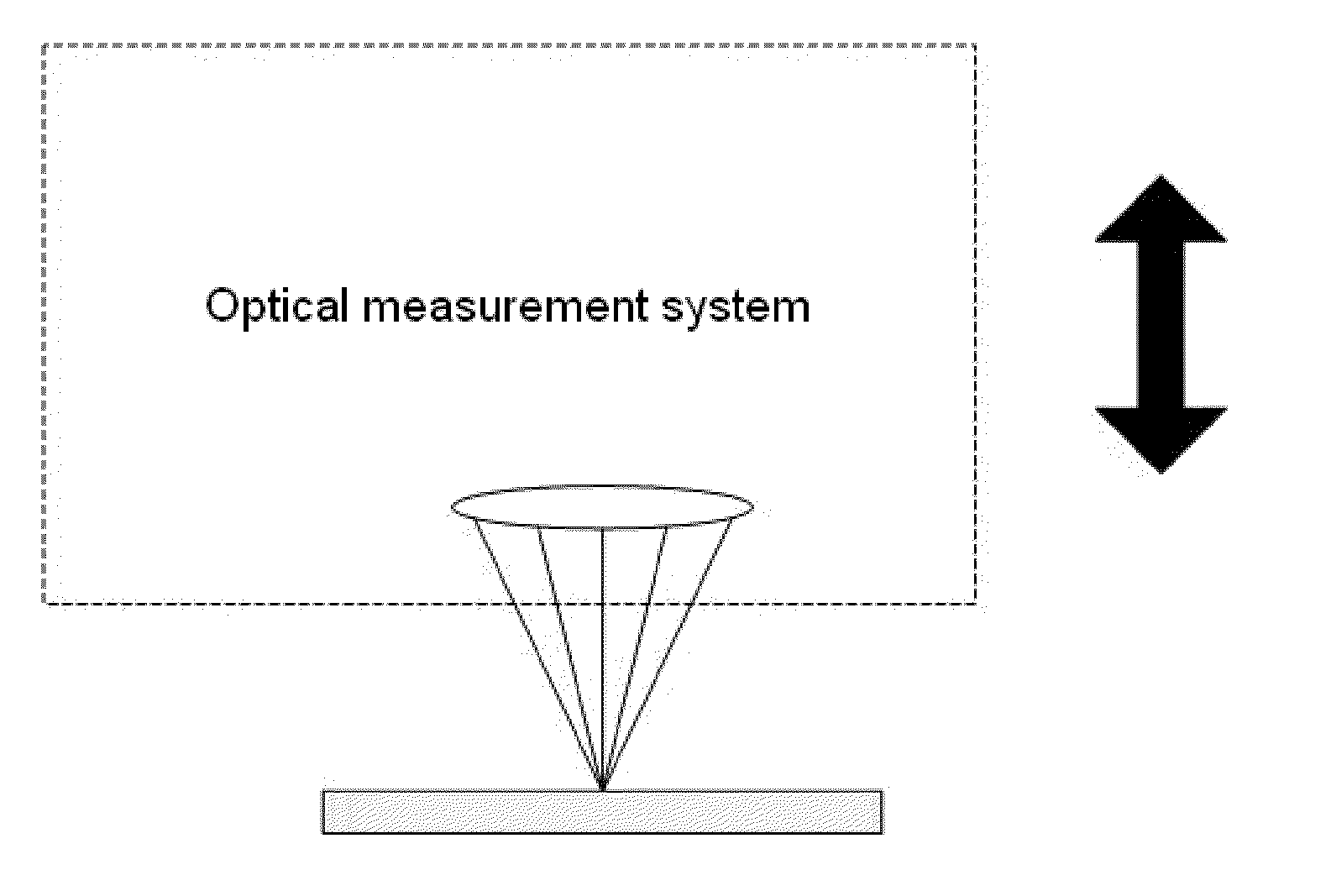
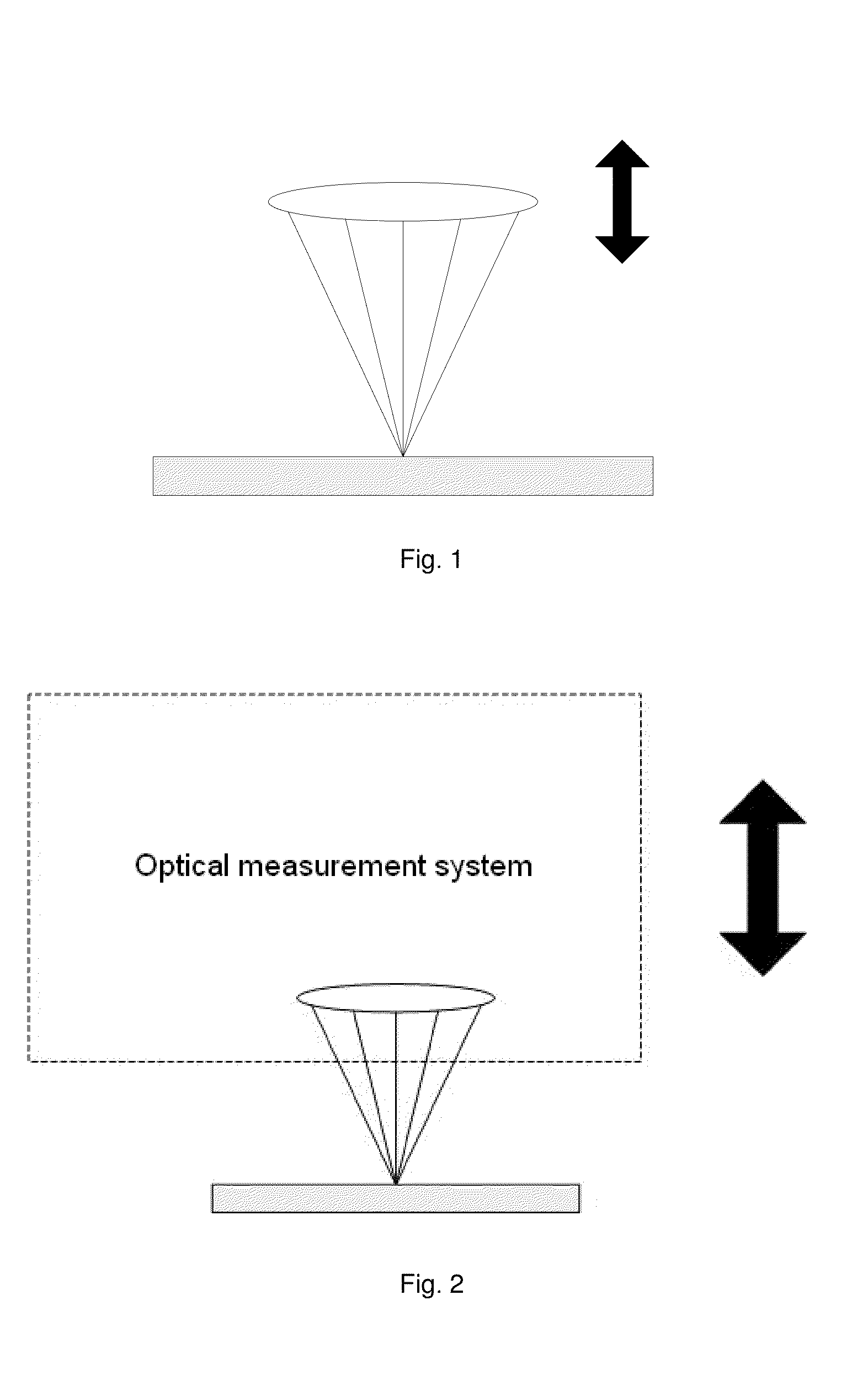
TECHNICAL FIELD OF THE INVENTION[0001]The disclosure relates to the field of optics, and in particular to a normal-incidence broadband spectroscopic polarimeter containing reference beam and an optical measurement system.BACKGROUND OF THE INVENTION[0002]Generally, a key step in optical measurement technique is to make the probing beam focused onto the sample. Two methods are currently widely used. One method is to separate the last focusing lens from other components and only to adjust the focusing lens to focus the probing beam onto the sample. For example, as shown in FIG. 1, the focusing is achieved by moving the last focusing lens up and down. The other method is to adjust the whole optical measurement system to focus the probing beam on the sample. For example, as shown in FIG. 2, the focusing is achieved by moving the whole optical system up and down (for example, refer to the U.S. Pat. No. 5,747,813 and U.S. Pat. No. 5,486,701).[0003]With the rapid development of semiconducto...

Claims


Application Information

Patent Timeline
IPC IPC(8): G01J3/447G01B11/02
CPCG01B11/02G01J3/447G01B2210/56G01J3/0208G01J3/0224G01J3/42G01N21/21G01N2021/213G02B27/14G02B27/40
Inventor LI, GUOGUANGLIU, TAOZHAO, JIANGYANGUO, QINGYANGGENIO, EDGARMA, TIEZHONGXIA, YANG
Owner BEI OPTICS TECHNOLOGY COMPANY LIMITED
Why Eureka
Try Eureka