
Method for manufacturing semiconductor device

Active Publication Date: 2014-12-04
INST OF MICROELECTRONICS CHINESE ACAD OF SCI
View PDF2 Cites 3 Cited by
  • Summary
  • Abstract
  • Description
  • Claims
  • Application Information

AI Technical Summary

Benefits of technology

The present invention provides a method for manufacturing a semiconductor device that can effectively reduce the SBH (semiconductor-silicon contact barrier) and decrease the contact resistance. This is achieved by annealing after implanting doping ions into the Ni-rich phase of metal silicide, which improves the solid solubility of the doping ions and forms a segregation region of highly concentrated doping ions. This reduces the SBH between the nickel-based metal silicide and the source / drain region, resulting in improved driving capability of the device.

Problems solved by technology

The high electric field causes a series of reliability problems and degrades the device performance.
As shown in Table 1, according to the technology road map of 2010, the allowed maximum contact resistance of the Totally Depleted SOI (FDSOI) device will reach an order of 10−9 Ω-cm2, which brings a great challenge to the device design and manufacturing.
However, the above three methods are very limited.
Thus the process complexity is greatly increased and the method cannot be applied in the actual production.
However, the above method that reduces the SBH using the SADS still has the following deficiency: impurity ions implanted into the source / drain of the Nickel-based metal silicide have a poor solubility, and the implanted large quantity of ions cannot be solid-soluble in the Nickel-based metal silicide, thus the number of the doping ions available for reducing the SBH is not enough.
But the temperature of the driving annealing is low and is not sufficient to completely activate the segregated impurities, thus the SBH is not obviously reduced.
Therefore, the above conventional method is not enough to reduce the SBH to a level below 0.1 eV.
In summary, the existing MOSFET cannot effectively reduce the SBH, and then cannot effectively decrease the source / drain resistance RCSD while effectively improving the driving capability of the device.

Method used


Image

  • Method for manufacturing semiconductor device
  • Method for manufacturing semiconductor device
  • Method for manufacturing semiconductor device

Examples


Embodiment Construction

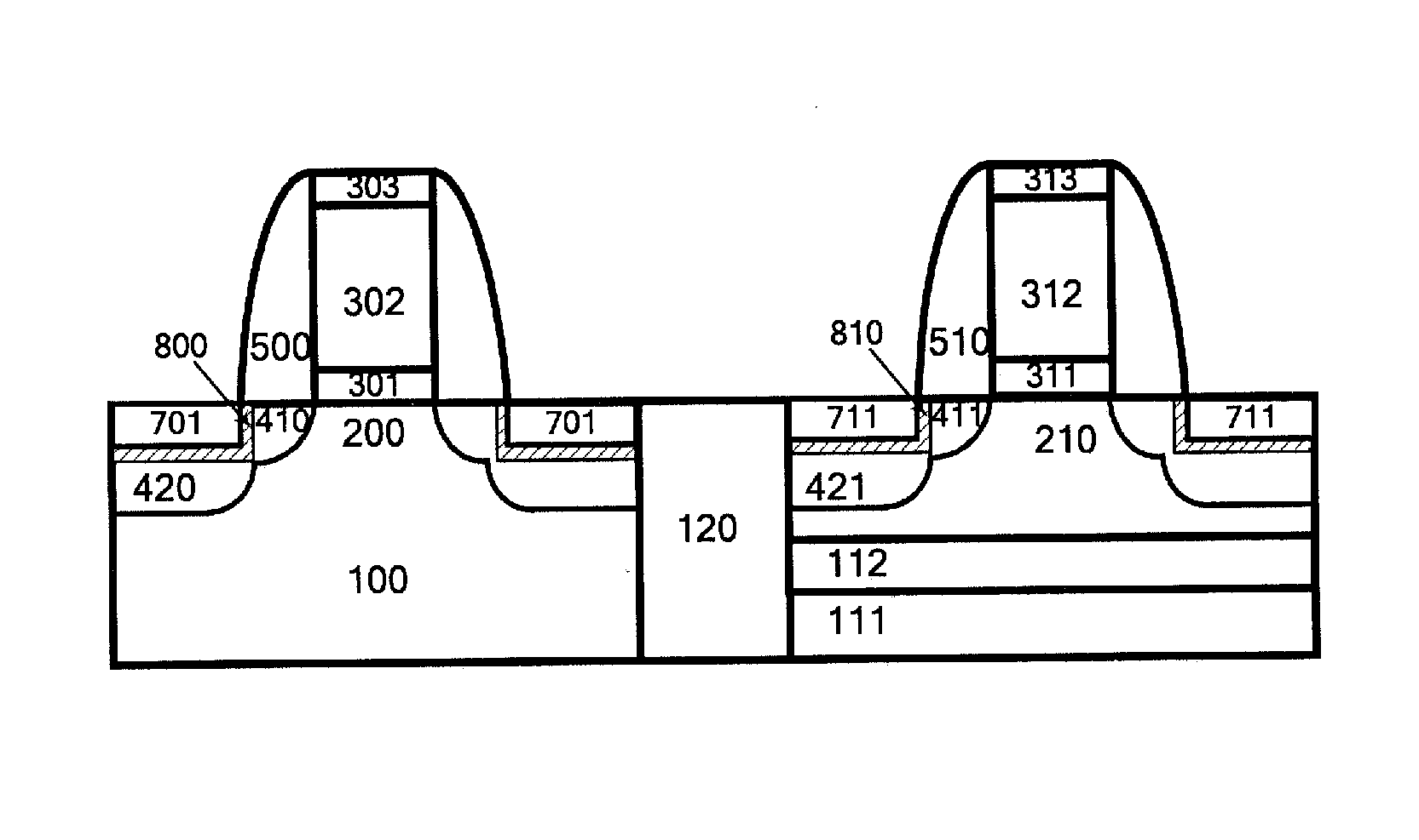
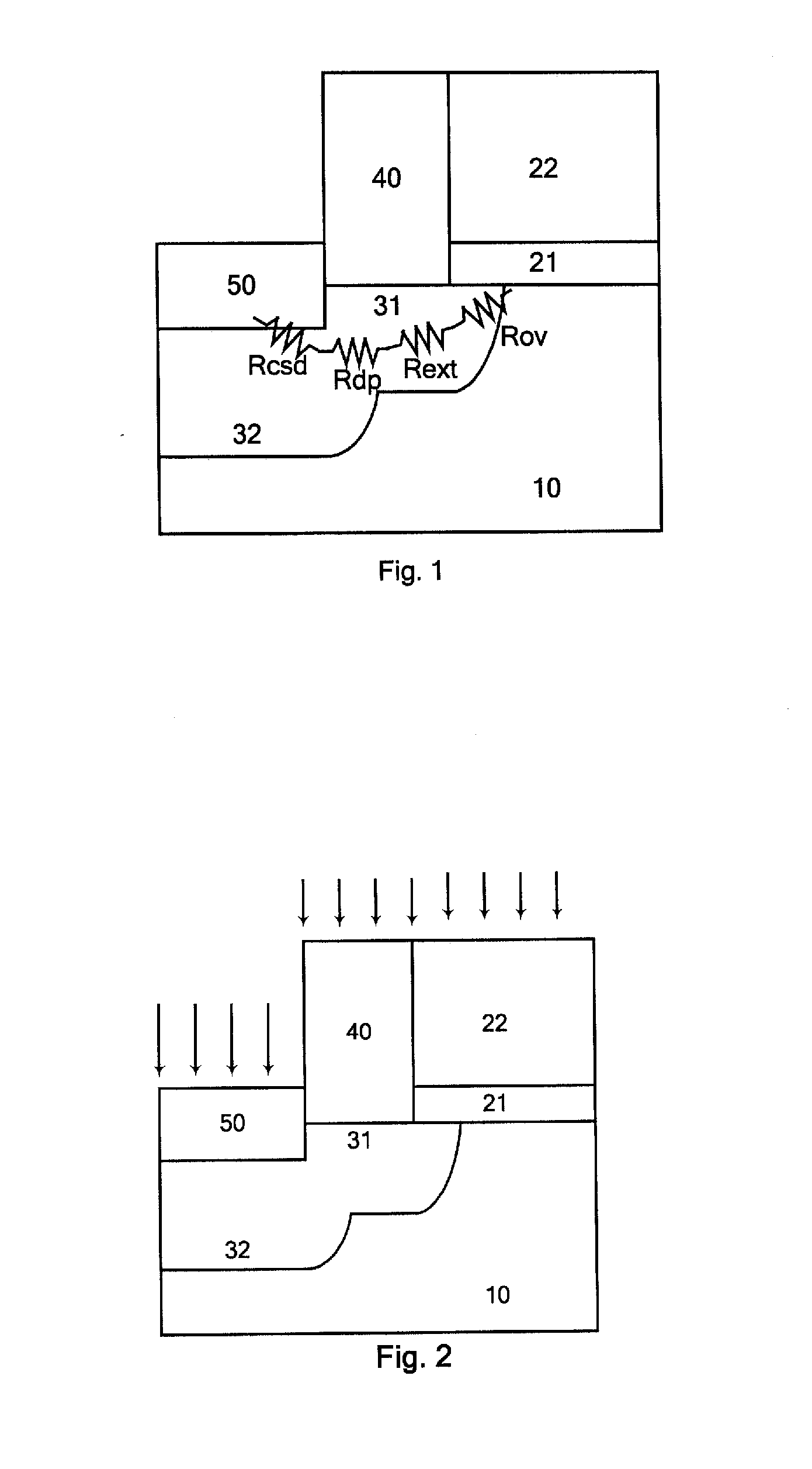
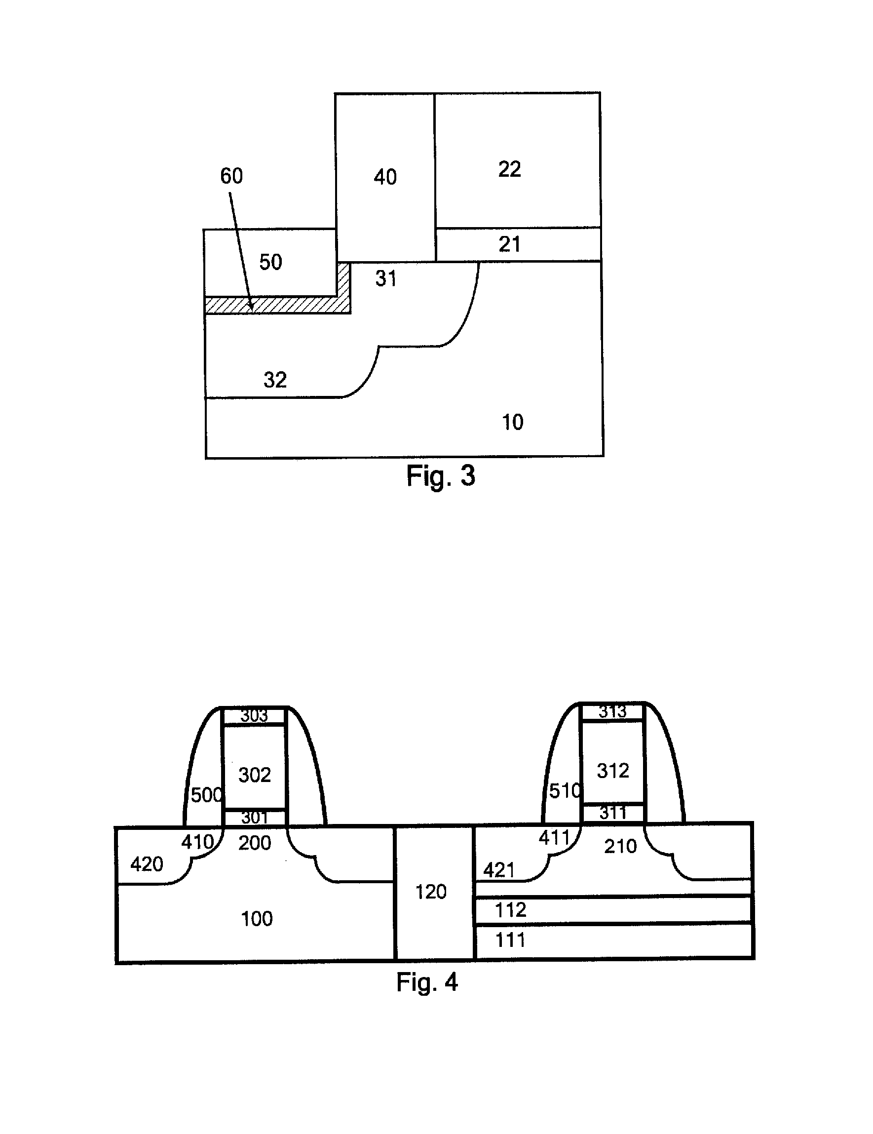
[0038]The characteristics and technical effects of the technical solutions of the present invention are detailedly described as follows with reference to the drawings and in conjunction with the exemplary embodiments, in which a method for manufacturing a semiconductor device capable of effectively reducing the SBH so as to decrease the contact resistance is disclosed. To be noted, the similar reference signs denote the similar structures. The terms such as “first”, “second”, “upper” and “lower” occurring in the present application can be used to modify various device structures or manufacturing procedures. Those modifications do not imply the spatial, sequential or hierarchical relationships between the modified device structures or manufacturing procedures unless otherwise specified.

[0039]Firstly as illustrated in FIG. 4, a substrate and a gate basic structure are formed.

[0040]For example, the isolation structure of an active region in a substrate may be formed firstly. A substrat...


PUM


Abstract

The present invention discloses a method for manufacturing a semiconductor device, comprising: forming a gate stacked structure on a substrate; forming a source / drain region and a gate sidewall spacer at both sides of the gate stacked structure; depositing a Nickel-based metal layer at least in the source / drain region; performing a first annealing so that the silicon in the source / drain region reacts with the Nickel-based metal layer to form a Ni-rich phase of metal silicide; performing an ion implantation by implanting doping ions into the Ni-rich phase of metal silicide; performing a second annealing so that the Ni-rich phase metal silicide is transformed into a Nickel-based metal silicide, and meanwhile, forming a segregation region of the doping ions at an interface between the Nickel-based metal silicide and the source / drain region. The method according to the present invention performs the annealing after implanting the doping ions into the Ni-rich phase of metal silicide, thereby improving the solid solubility of the doping ions and forming a segregation region of highly concentrated doping ions, thus the SBH of the metal-semiconductor contact between the Nickel-based metal silica and the source / drain region is effectively reduced, the contact resistance is decreased, and the driving capability of the device is improved.

Description

CROSS REFERENCE TO RELATED APPLICATIONS[0001]This application is a national stage application, filed under 35 U.S.C. §371, of PCT Patent Application Serial No. PCT / CN2012 / 072985, filed on Mar. 23, 2012, which claimed priority to Chinese Patent Application Serial No. 201110419334.9, filed on Dec. 15, 2011, all of which are hereby incorporated by reference in their entiretyFIELD OF THE INVENTION[0002]The present invention relates to a method for manufacturing a semiconductor device, and particularly, to a method for reducing the contact resistance of conventional highly doped source / drain MOSFET.BACKGROUND OF THE INVENTION[0003]The continuous increase of the IC integration level requires the device size to be constantly reduced in proportion. But sometimes the working voltage of the electric apparatus remains unchanged, and the actual electric field strength inside the MOS device continuously increases. The high electric field causes a series of reliability problems and degrades the d...

Claims


Application Information

Patent Timeline
IPC IPC(8): H01L21/8238H01L29/417H01L29/45H01L21/84
CPCH01L21/823814H01L21/84H01L29/45H01L29/41725H01L21/823878H01L21/2255H01L21/28518H01L29/456H01L29/665H01L21/823418H01L21/823443H01L21/823807
Inventor LUO, JUNZHAO, CHAOZHONG, HUICAILI, JUNFENGCHEN, DAPENG
Owner INST OF MICROELECTRONICS CHINESE ACAD OF SCI
Learn More