

Wireless communication system and method and expansion unit of flat network architecture
a flat network and communication system technology, applied in the field of wireless communication technologies, can solve the problems of system coefficient, system performance degradation, and difficulty and cost of system deploymen
- Summary
- Abstract
- Description
- Claims
- Application Information
AI Technical Summary
Benefits of technology
Problems solved by technology
Method used
Image

Examples
first embodiment
[0048]
[0049]As shown in FIG. 4, there is a schematic structural diagram of a wireless communication system of a flat network architecture according to the first embodiment of the invention, where the wireless communication system includes at least one baseband signal source 11, an EU 12 and at least one RU 13 connected with the EU 12.
[0050]The wireless communication system can support multiple wireless transmission modes including a Global System of Mobile communication (GSM), Wideband Code Division Multiple Access (WCDMA), Time Division-Synchronous Code Division Multiple Access (TD-SCDMA), Long Term Evolution (LTE), a Wireless Local Area Network (WLAN) and the like.
[0051]The wireless communication system can support the signal processing in any one of the above modes or can concurrently support the hybrid processing of multiple signals in more than one of the above modes, that is, the wireless communication system can support the processing of single-mode or multimode signals.
[0052...
second embodiment
[0094]
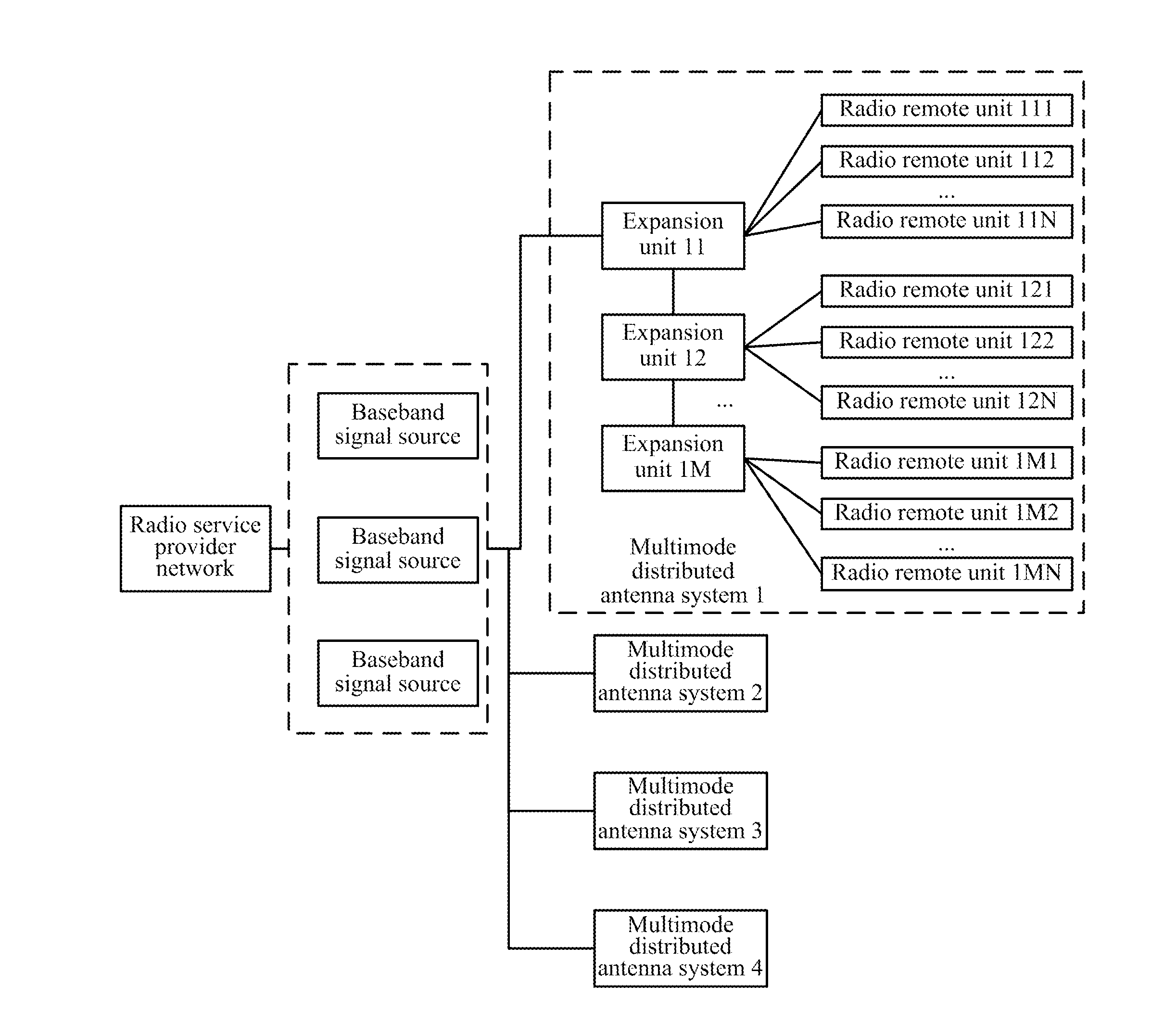
[0095]In the wireless communication system according to the embodiment of the invention, the baseband signal sources can be cascaded for network deployment. As shown in FIG. 5, there is a schematic structural diagram of a wireless communication system adopting a networking mode where baseband signal sources are cascaded. The wireless communication system includes a radio service provider network, multiple baseband signal sources, multiple EUs and at least one RU connected with the respective EUs, where the respective baseband signal sources further include cascade interfaces.
[0096]The respective baseband signal sources are connected sequentially via the local cascade interfaces, where the firstly arranged baseband signal source and the lastly arranged baseband signal source each is connected with a baseband signal source via the local cascade interface, and the remaining base band signal sources each is connected with two baseband signal sources via the local cascade interface...
third embodiment
[0102]
[0103]In the wireless communication system according to the embodiment of the invention, the baseband signal sources can alternatively be stacked for network deployment. As shown in FIG. 6, there is a schematic structural diagram of a wireless communication system adopting a networking mode where baseband signal sources are stacked. The wireless communication system includes a radio service provider network, an EU, at least one RU connected with the EU, and multiple baseband signal sources, where one of the baseband signal sources is a master baseband signal source, and the remaining baseband signal sources are subordinate baseband signal sources, and the respective baseband signal sources further include stacking interfaces.
[0104]The master baseband signal source is connected respectively with the radio service provider network and the EU, and the subordinate baseband signal sources are connected sequentially via the local stacking interfaces, where the first subordinate base...
PUM
 Abstract
Description
Claims
Application Information