Dispersion compensation fiber

a fiber and fiber technology, applied in the field of dispersion compensation fibers, can solve the problems of low splice efficiency, easy leakage, and inability to use, and achieve the effects of reducing splice loss, reducing mode field mismatching, and significantly improving splice efficiency

Active Publication Date: 2014-12-18
YANGTZE OPTICAL FIBRE & CABLE CO LTD
View PDF10 Cites 6 Cited by
  • Summary
  • Abstract
  • Description
  • Claims
  • Application Information

AI Technical Summary

Benefits of technology

[0031]1. The present invention provides a DCF with doped core layer and claddings; the trench cladding, annular cladding, and matching cladding are subject to a discharge effect of a splicer, and elements near the contact are dispersed, which causes the refractive index to change; hence, a conical transitional mode field area is formed, thereby reducing the mode field mismatching and reducing splice loss.
[0032]2. The DCF of the present invention has appropriate element structural distribution, so that the viscosity of the core layer and the claddings are matched, implementing fast splice between the DCF and the SMF. Therefore, time for splicing one contact is reduced to 90 s, and even less than...

Problems solved by technology

At this time, the splice loss between the DCF and the standard communication fiber becomes an important impact factor of insertion loss.
As a result of such difference in the mode field (mode field mismatching), leakage easily occurs when optical power is introduced from a large mode field to a small mode field.
The U.S. Pat. No. 6,543,942 describes a method for connecting a DCF and a standard single mode fiber by using a bridge fiber, which reduces the splice loss, but the patent does not correspondingly disclose the optical transmission performance of the DCF; in...

Method used


Image

  • Dispersion compensation fiber
  • Dispersion compensation fiber
  • Dispersion compensation fiber

Examples


Embodiment Construction

[0040]The present invention is more particularly described in the following examples that are intended as illustrative only since numerous modifications and variations therein will be apparent to those skilled in the art. Various embodiments of the invention are now described in detail in conjunction with the accompanying drawings. Referring to the drawings, like numbers indicate like components throughout the views.

[0041]In accordance with the purposes of this invention, as embodied and broadly described herein, this invention, in one aspect, relates to a dispersion compensation fiber (DCF).

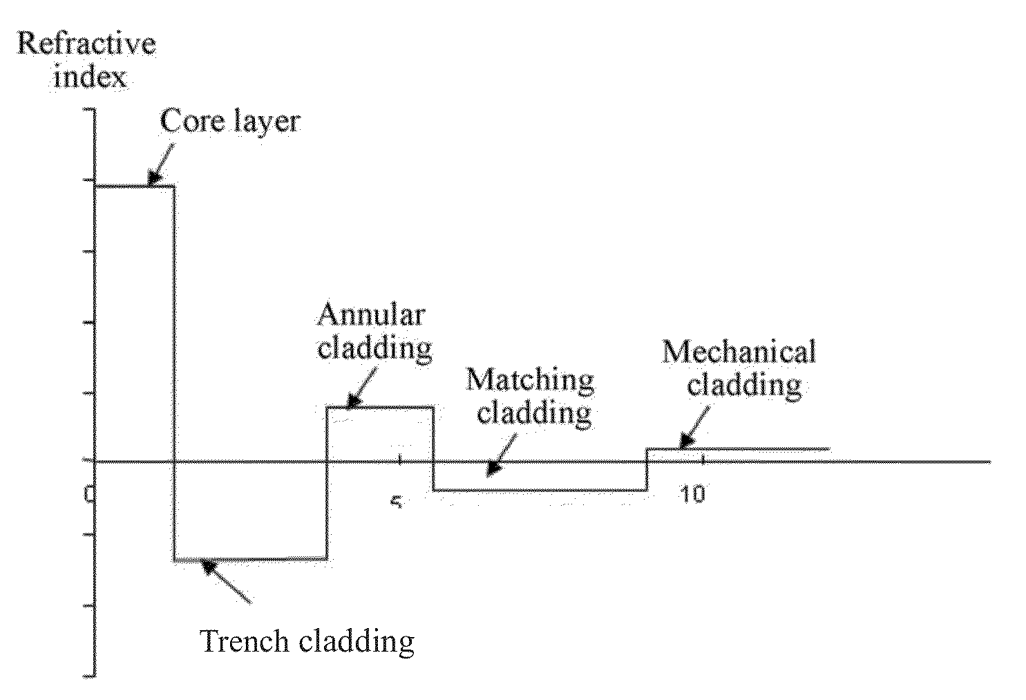
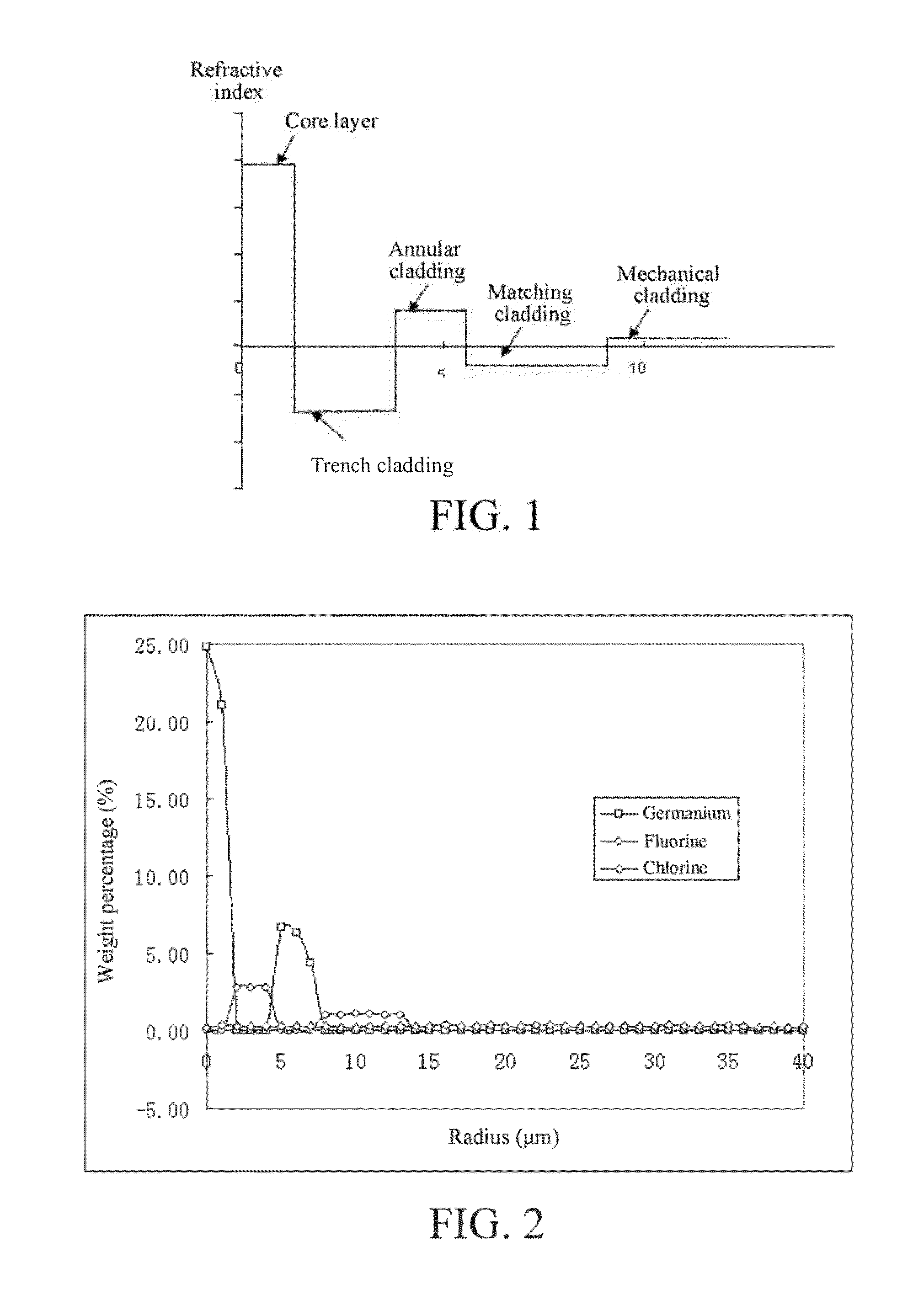
[0042]Referring to FIG. 1, a composition structure of a DCF is schematically shown in FIG. 1 according to the present invention. The fibers with different performance parameters are obtained by changing weight percentages of elements in the layers according to various embodiments of the present invention. In the embodiments, a PCVD process is adopted to manufacture a core rod of a fiber preform,...


PUM


Abstract

A dispersion compensation fiber comprises a fiber core and cladding. The fiber core is a core layer mainly doped with germanium and having a positive relative refractive index difference. The cladding covering the fiber core comprises a trench cladding mainly doped with fluorine, an annular cladding mainly doped with germanium, a matching cladding mainly doped with fluorine, and an outermost mechanical cladding in order. Relative refractive index differences of the fiber core and the claddings are respectively: Δ1% being 1.55% to 2.20%, Δ2% being −0.55% to −0.30%, Δ3% being 0.40% to 0.65%, Δ4% being −0.20% to −0.01%, and Δ5% being 0. Radius ranges, from R1 to R5, of the fiber core and the claddings are respectively: R1 being 1.4 to 1.7 μm, R2 being 4.1 to 4.8 μm, R3 being 6.7 to 8.8 μm, R4 being 10 to 17 μm, and R5 being 38 to 63 μm.

Description

FIELD OF THE INVENTION[0001]The present invention relates to a dispersion compensation fiber (DCF) working at an optical communication window of a C waveband (a waveband from 1530 nm to 1565 nm). The fiber is usable for compensating dispersion and a dispersion slope of a standard single mode fiber (G.652, ITU-T standard).BACKGROUND OF THE INVENTION[0002]With the popularization of a dense wavelength division multiplexing (DWDM) system of a standard single mode fiber, and the development trend towards high speed, long distance, non-relay and dense channels, the wavelength division multiplexing technology is developed rapidly; and the working wavelength band is rapidly expanded, and the wavelength is diversified rapidly.[0003]At the wavelength of 1310 nm, a long-haul fiber constructed based on G.652 fibers has minimum dispersion, but has significant attenuation, while at the waveband of 1550 nm, the long-haul fiber has lowest attenuation (about 0.20 dB / km). Therefore, people are eager ...

Claims


Application Information

Patent Timeline
IPC IPC(8): G02B6/036G02B6/27H04B10/2525
CPCG02B6/27G02B6/036G02B6/02214G02B6/03644G02B6/02261G02B6/03666G02B6/02G02B6/028
Inventor ZHANG, SHUQIANGFAN, MINGFENGWANG, SONGXU, JINLUO, JIECAO, BEIBEI
Owner YANGTZE OPTICAL FIBRE & CABLE CO LTD
Why Eureka
Try Eureka