Imaging device and endoscope apparatus including the same

Inactive Publication Date: 2014-12-18
FUJIFILM CORP
View PDF4 Cites 27 Cited by
  • Summary
  • Abstract
  • Description
  • Claims
  • Application Information

AI Technical Summary

Benefits of technology

The patent is about a method to capture images using a rolling shutter type imaging element and a pulsed light source. The method ensures that each line of the element receives a consistent amount of light, resulting in images that have brightness unevenness. The invention provides an imaging device and an endoscope apparatus that can achieve both a wide dimming dynamic range and high dimming resolution without changing the amount of received light.

Problems solved by technology

However, in the driving using only the same modulation method, a dimming dynamic range may be insufficient.
Accordingly, dimming resolution may be insufficient in the area of a low amount of light.
In addition, when the exposure time by the shutter is fixed to the maximum exposure time, a fast moving subject may be blurred.
Thus, when imaging is performed using a rolling shutter type imaging element under the illumination light from the pulsed light source, neither the necessary and sufficient image quality nor dimming performance can be obtained.

Method used


Image

  • Imaging device and endoscope apparatus including the same
  • Imaging device and endoscope apparatus including the same
  • Imaging device and endoscope apparatus including the same

Examples


Embodiment Construction

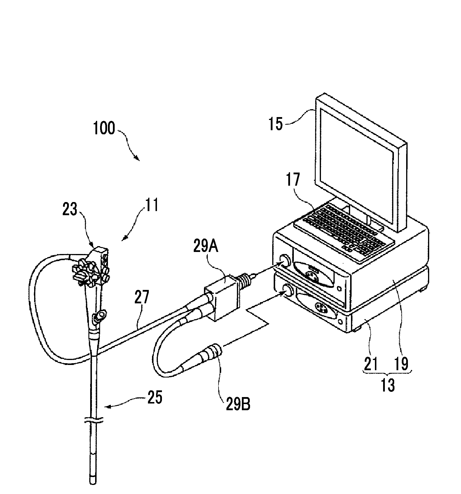
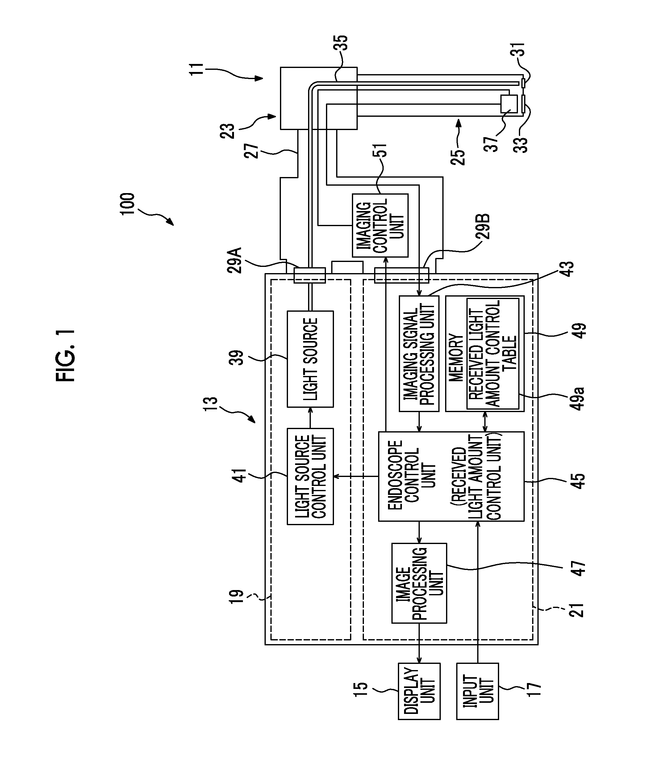
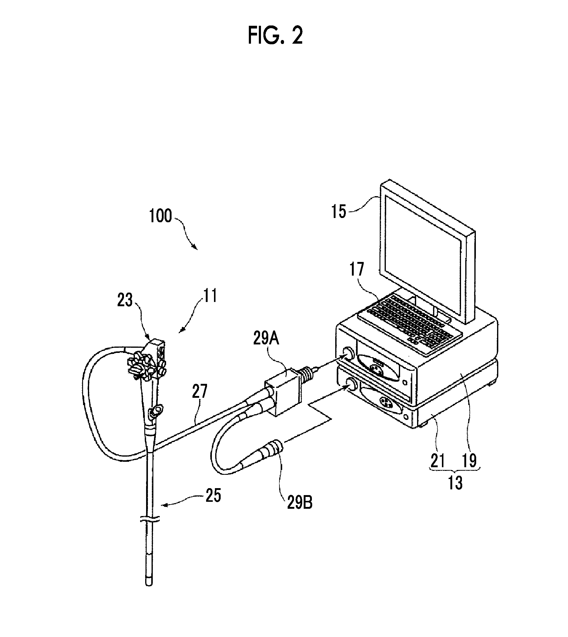
[0028]Hereinafter, an embodiment of the present invention will be described in detail with reference to the diagrams. FIG. 1 is a diagram for explaining the embodiment of the present invention, and is a block diagram showing the schematic configuration of an endoscope apparatus. FIG. 2 is an external view showing an example of the specific configuration of the endoscope apparatus.

Configuration of the Endoscope Apparatus

[0029]As shown in FIGS. 1 and 2, an endoscope apparatus 100 includes an endoscope 11, a control device 13 to which the endoscope 11 is connected, a display unit 15 connected to the control device 13, such as a liquid crystal monitor, and an input unit 17 to input information to the control device 13, such as a keyboard or a mouse. The control device 13 is configured to include a light source device 19 that generates illumination light and a processor 21 that performs signal processing or the like on a captured image.

[0030]The endoscope 11 includes a body operation uni...


PUM


Abstract

A wide dimming dynamic range and high dimming resolution are obtained without causing a variation in the amount of received light due to pulse illumination light in each line of an imaging element. An imaging device includes a light source emitting light by pulse driving, a light source control unit controlling the amount of emitted light by performing pulse modulation driving of the light source, and an imaging unit including an imaging element, in which a plurality of pixels are arrayed in a horizontal and vertical direction, and performs imaging by driving the imaging element using a rolling shutter method. The light source control unit performs pulse driving of the light source at a timing synchronized with a timing pulse signal having, as a period, 1 / p (p is an integer of 1 or more) of the exposure start timing interval when driving the imaging element using the rolling shutter method.

Description

CROSS-REFERENCE TO RELATED APPLICATIONS[0001]This application is a Continuation of PCT International Application No. PCT / JP2013 / 058943 filed on Mar. 27, 2013, which claims priority under 35 U.S.C. §119(a) to Patent Application No. 2012-074245 filed in Japan on Mar. 28, 2012, Patent Application No. 2013-047904 filed in Japan on Mar. 11, 2013, and PCT International Application No. PCT / JP2013 / 054975 filed on Feb. 26, 2013, all of which are hereby expressly incorporated by reference into the present application.BACKGROUND OF THE INVENTION[0002]1. Field of the Invention[0003]The present invention relates to an imaging device and an endoscope apparatus including the same.[0004]2. Description of the Related Art[0005]A general endoscope apparatus generates an observation image by emitting white light from a white light source such as a xenon lamp, as illumination light, to an observation area in a body cavity through a light guide and capturing reflected light images due to the emission of ...

Claims


Application Information

Patent Timeline
IPC IPC(8): A61B1/07A61B1/045A61B1/06
CPCA61B1/07A61B1/045A61B1/0661A61B1/00006A61B1/00009G02B23/2461G02B23/2484A61B1/0655H04N23/00H04N23/555
Inventor SETO, YASUHIRO
Owner FUJIFILM CORP
Why Eureka
Try Eureka