Apparatus for in-situ production of low dissolved hydrogen sulfide, degassed, sulfur from claus sulfur recovery

a technology of hydrogen sulfide and in-situ production, which is applied in the direction of lighting and heating apparatus, sulfur preparation/purification, and separation processes, etc. it can solve the problems of limiting the sulfur processing capability of the claus/tgu unit, unintended exposure, and undesired mixture formation in open air storage vessels

Active Publication Date: 2014-12-25
PHILLIPS 66 CO
View PDF9 Cites 4 Cited by
  • Summary
  • Abstract
  • Description
  • Claims
  • Application Information

AI Technical Summary

Benefits of technology

[0013]A process of producing degassed liquid sulfur, such as in a vertical sulfur condenser, may include providing a Claus process gas inlet to a casing of a sulfur condenser, introducing a Claus process gas into the sulfur condenser, providing a condenser tube that protrudes into a liquid reservoir. The liquid reservoir may be a mixture of liquid sulfur and a catalyst. The process may further include passing the Claus process gas through the condenser tubes, condensing elemental sulfur containing dissolved H2S and chemically reacted H2S in the form of H2Sx (where x>1) from the Claus process gas on the condenser tube, and collecting the contaminated condensed Claus sulfur in the liquid reservoir. The process may further include passing the cooled process gas and condensed sulfur from the tubes through the reservoir of liquid sulfur containing the catalyst creating a contacting zone for the process gas, contaminated sulfur, and the catalyst facilitating the contact between the liquid sulfur in the reservoir, the catalyst, and the remaining Claus process gas causing catalytic decomposition of the polysulfanes to H2S and sulfur and reaction on the catalyst between hydrogen sulfide and sulfur dioxide to form sulfur and water vapor thereby producing degassed liquid sulfur. The liquid reservoir with degassed liquid sulfur may be drained and the Claus process gas may be passed downstream.
[0014]A process of producing degassed sulfur, such as in a horizontal sulfur condenser, may include providing a Claus process gas inlet in a first end of a casing

Problems solved by technology

Accumulations of emanated H2S can lead to unintended exposures during loading of sulfur and during storage of sulfur in open air containers, such as underground concrete pits that facilitate gravity drainage or tanks vented with air.
Emanate

Method used


Image

  • Apparatus for in-situ production of low dissolved hydrogen sulfide, degassed, sulfur from claus sulfur recovery
  • Apparatus for in-situ production of low dissolved hydrogen sulfide, degassed, sulfur from claus sulfur recovery
  • Apparatus for in-situ production of low dissolved hydrogen sulfide, degassed, sulfur from claus sulfur recovery

Examples


Embodiment Construction

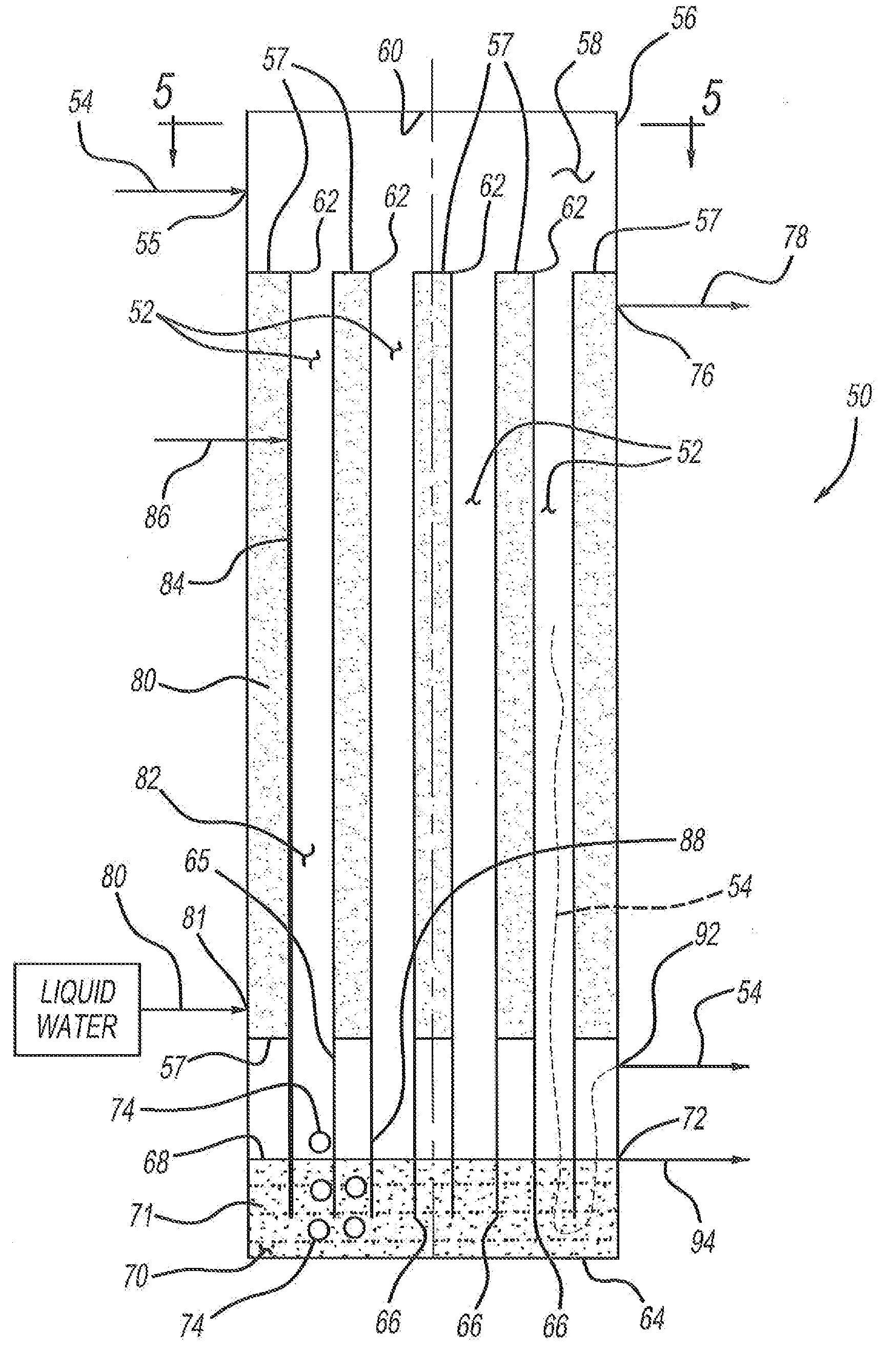
[0026]In conjunction with FIGS. 3-10, exemplary embodiments and processes of the present disclosure will be explained. FIG. 3 is an overall schematic depicting components of the teachings of the present disclosure, including condenser 44, which may be a vertical or horizontal Claus sulfur condenser as depicted in FIGS. 4-8. In a Claus sulfur recovery process 36, a burner 38 receives feed acid gas and either air or a combination of air and pure oxygen. Combustion products of the exothermic reaction evolve into a reaction furnace 40 where endothermic reactions of the Claus process take place. The effluent from reaction furnace 40 passes through a heat exchanger 42 where it is cooled, and then to a condenser 44. Liquid sulfur condenses and may be introduced into a vessel 46, which may be a float type trap or barometric seal leg used to maintain pressure on the process gases. Liquid sulfur may then pass into an underground sulfur storage pit 48 or an above ground tank. Although FIG. 3 d...


PUM

PropertyMeasurementUnit
Depthaaaaaaaaaa
Distanceaaaaaaaaaa

Abstract

A horizontal sulfur condenser may include an exterior casing with a plurality of condenser tubes arranged longitudinally within the casing, a liquid sulfur reservoir at a longitudinal end within the exterior casing, and an internal baffle that protrudes into the liquid sulfur reservoir from the surface. The lowest of the plurality of condenser tubes is parallel to a wall of the exterior casing. A Claus process gas inlet is proximate a first end of the plurality of condenser tubes, which are arranged horizontally but are positioned vertically above the sulfur reservoir. A liquid sulfur outlet is located at the liquid sulfur surface. The baffle creates multiple chambers above the sulfur reservoir, such as a first chamber defined by the exterior casing and the baffle to receive condensed Claus sulfur in the liquid reservoir, and a second chamber defined by the exterior casing and the baffle to receive degassed liquid sulfur.

Description

CROSS-REFERENCE TO RELATED APPLICATIONS[0001]This application is a non-provisional application which claims benefit under 35 USC §119(e) to U.S. Provisional Application Ser. No. 61 / 837,927 filed Jun. 21, 2013, entitled “APPARATUS FOR IN-SITU PRODUCTION OF LOW DISSOLVED HYDROGEN SULPHIDE, DEGASSED, SULFUR FROM CLAUS SULFUR RECOVERY,” and to U.S. Provisional Application Ser. No. 61 / 837,944 filed Jun. 21, 2013, entitled “APPARATUS FOR IN-SITU PRODUCTION OF LOW DISSOLVED HYDROGEN SULPHIDE, DEGASSED, SULFUR FROM CLAUS SULFUR RECOVERY,” and to U.S. Provisional Application Ser. No. 61 / 837,950 filed Jun. 21, 2013, entitled “PROCESS FOR IN-SITU PRODUCTION OF LOW DISSOLVED HYDROGEN SULPHIDE, DEGASSED, SULFUR FROM CLAUS SULFUR RECOVERY,” and to U.S. Provisional Application Ser. No. 61 / 837,958 filed Jun. 21, 2013, entitled “PROCESS FOR IN-SITU PRODUCTION OF LOW DISSOLVED HYDROGEN SULPHIDE, DEGASSED, SULFUR FROM CLAUS SULFUR RECOVERY,” and to U.S. Provisional Application Ser. No. 62 / 010,766 file...

Claims


Application Information

Patent Timeline
IPC IPC(8): B01D53/00
CPCB01D53/002B01D5/0012B01D5/0051B01D5/0093C01B17/0232C01B17/0456C01B17/0439C01B17/0469C01B17/0447B01D5/0009B01J8/02B01D5/00B01D5/0069C01B17/05F25J1/00F25J1/0002
Inventor KELLER, ALFRED E.
Owner PHILLIPS 66 CO
Why Eureka
Try Eureka