Overcurrent detection apparatus and intelligent power module using same

a detection apparatus and power module technology, applied in the direction of automatic balancing arrangements, pulse techniques, instruments, etc., can solve the problems of unsolved, lengthen the determination time required to determine the overcurrent condition, and reduce the size of the overall configuration

Active Publication Date: 2014-12-25
FUJI ELECTRIC CO LTD
View PDF2 Cites 23 Cited by
  • Summary
  • Abstract
  • Description
  • Claims
  • Application Information

AI Technical Summary

Benefits of technology

[0031]According to the present invention, the sense emitter corrected voltage calculated by subtracting the correction voltage, which is detected by the corrected current detection unit and corresponds to the current flowing between the gate and the sense emitter of the IGBT, from the sense emitter voltage of the IGBT, which is detected by the sense emitter current detection unit, is compared with an overcurrent threshold voltage. Hence, an overcurrent determination is performed using a net sense emitter voltage corres

Problems solved by technology

Hence, a problem remains unsolved in that when an overcurrent condition occurs, a determination time required to determine the overcurrent condition lengthens.
Likewise in this respect, a problem remains unsolved in that the determination time required to determine an overcurrent condition lengthens.
As a result, simultaneous detection of a short circuit current, which requires that the determination be performed quickly, is

Method used


Image

  • Overcurrent detection apparatus and intelligent power module using same
  • Overcurrent detection apparatus and intelligent power module using same
  • Overcurrent detection apparatus and intelligent power module using same

Examples


first embodiment

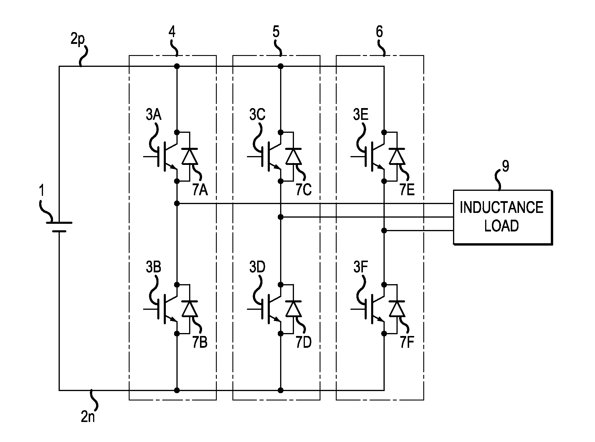
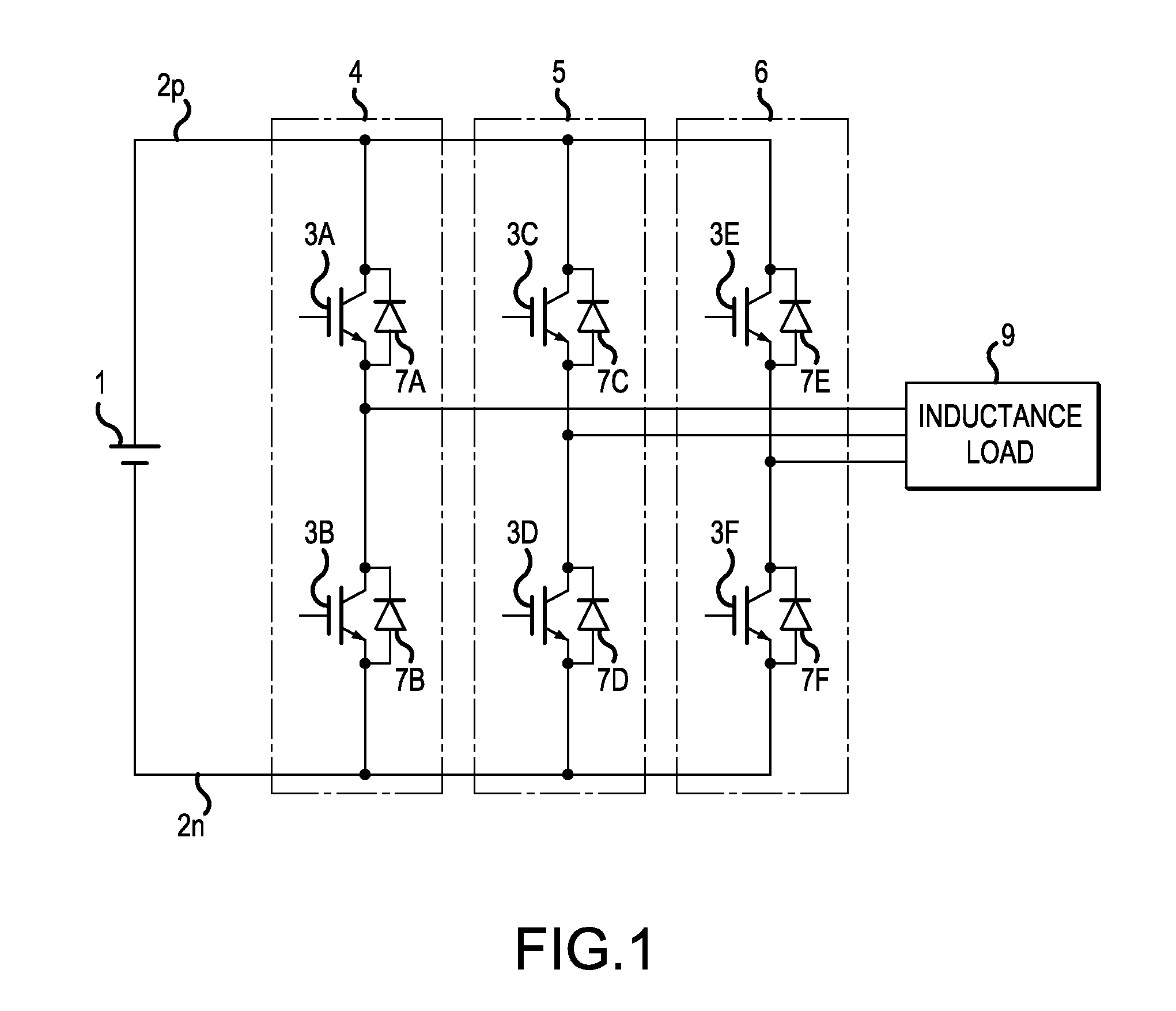
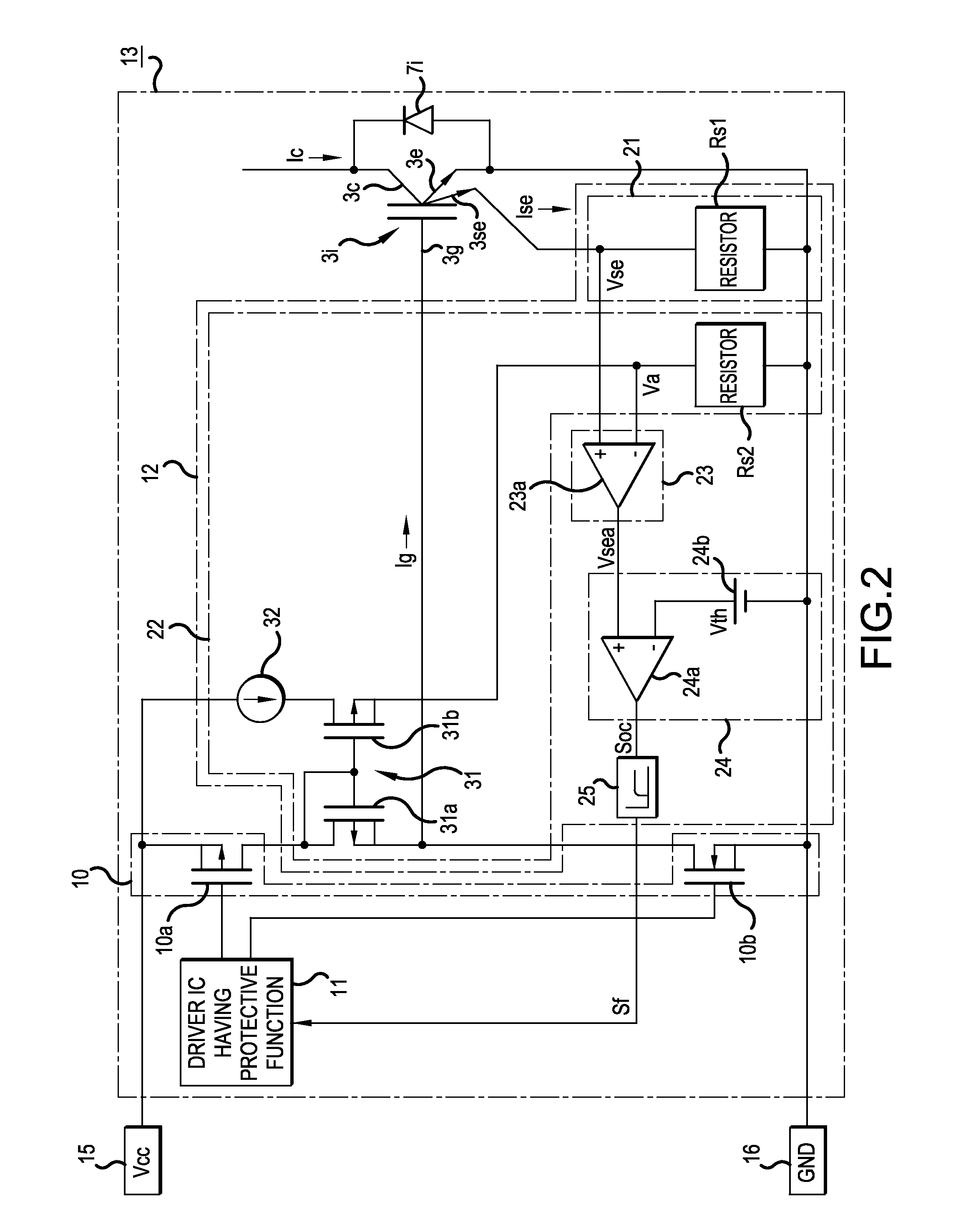
[0040]FIG. 1 is a circuit diagram showing a power conversion apparatus to which the present invention may be applied, and FIG. 2 is a circuit diagram showing an intelligent power module including an overcurrent detection apparatus according to the present invention.

[0041]As shown in FIG. 1, the power conversion apparatus to which the present invention may be applied is constituted by an inverter circuit that converts direct current power into three-phase alternating current power, for example. The inverter circuit includes a positive electrode side line 2p connected to a positive electrode side of a main direct current power supply 1, and a negative electrode side line 2n connected to a negative electrode side of the main direct current power supply 1.

[0042]A series circuit 4 in which insulated gate bipolar transistors (“IGBT”) 3A and 3B are connected in series, a series circuit 5 in which IGBTs 3C and 3D are connected in series, and a series circuit 6 in which IGBTs 3E and 3F are c...

second embodiment

[0079]Next, the present invention will be described with reference to a circuit diagram shown in FIG. 4.

[0080]In the second embodiment, the configuration of the correction current detection unit 22 is modified. More specifically, in the second embodiment, as shown in FIG. 4, the current mirror circuit 31 and the constant current circuit 32 are omitted from the correction current detection unit 22, and instead, a P-channel MOSFET 33 driven by a gate control signal of a driver IC 11 having a protective function is provided. A drain of the P-channel MOSFET 33 is connected to the control power supply 15, and a source is connected to the high potential side of the current detection resistor Rs2.

[0081]Here, the P-channel MOSFET 33 is set at a smaller cell size than the P-MOSFET 10a of the IGBT drive circuit 10. In this case, a cell size ratio between the P-channel MOSFETs 10a and 33 is set to be equal to the current mirror ratio of the current mirror circuit 31 described above and a corre...


PUM


Abstract

An overcurrent detection apparatus includes a sense emitter current detection unit that detects a sense emitter current output from a sense emitter of an IGBT as a sense emitter voltage, and a comparison unit that detects an overcurrent by comparing the sense emitter voltage detected by the sense emitter current detection unit with a threshold voltage. The overcurrent detection apparatus also includes a correction current detection unit that detects a correction current corresponding to a current flowing between a gate and the sense emitter of the IGBT as a corrected voltage; and a voltage correction unit that calculates a sense emitter corrected voltage by subtracting the correction voltage detected by the corrected current detection unit from the sense emitter voltage detected by the sense emitter current detection unit, and supplies the sense emitter corrected voltage to the comparison unit.

Description

CROSS-REFERENCE TO RELATED APPLICATIONS[0001]This application is a continuation of International Application No. PCT / JP2013 / 002262, filed on Apr. 1, 2013, and is based on and claims priority to Japanese Patent Application No. JP 2012-140931, filed on Jun. 22, 2012. The disclosure of the Japanese priority application and the PCT application in their entirety, including the drawings, claims, and the specification thereof, are incorporated herein by reference.BACKGROUND[0002]1. Field of the Invention[0003]Embodiments of the present invention relate to an overcurrent detection apparatus that protects an insulated gate bipolar transistor (“IGBT”) from breakage when an overcurrent flows through the IGBT, and also relates an intelligent power module using the same.[0004]2. Discussion of the Background[0005]A three-phase inverter circuit constituting a power conversion apparatus is configured by connecting series circuits, in which two each of six IGBTs and six freewheeling diodes (“FWD”) c...

Claims


Application Information

Patent Timeline
IPC IPC(8): G01R17/02G01R19/00H02M1/00
CPCG01R19/0092G01R17/02H02M1/08H02M1/32H03K17/0828H03K2217/0027G01R19/16547H02M1/0009
Inventor MINAGAWA, KEI
Owner FUJI ELECTRIC CO LTD
Why Eureka
Try Eureka