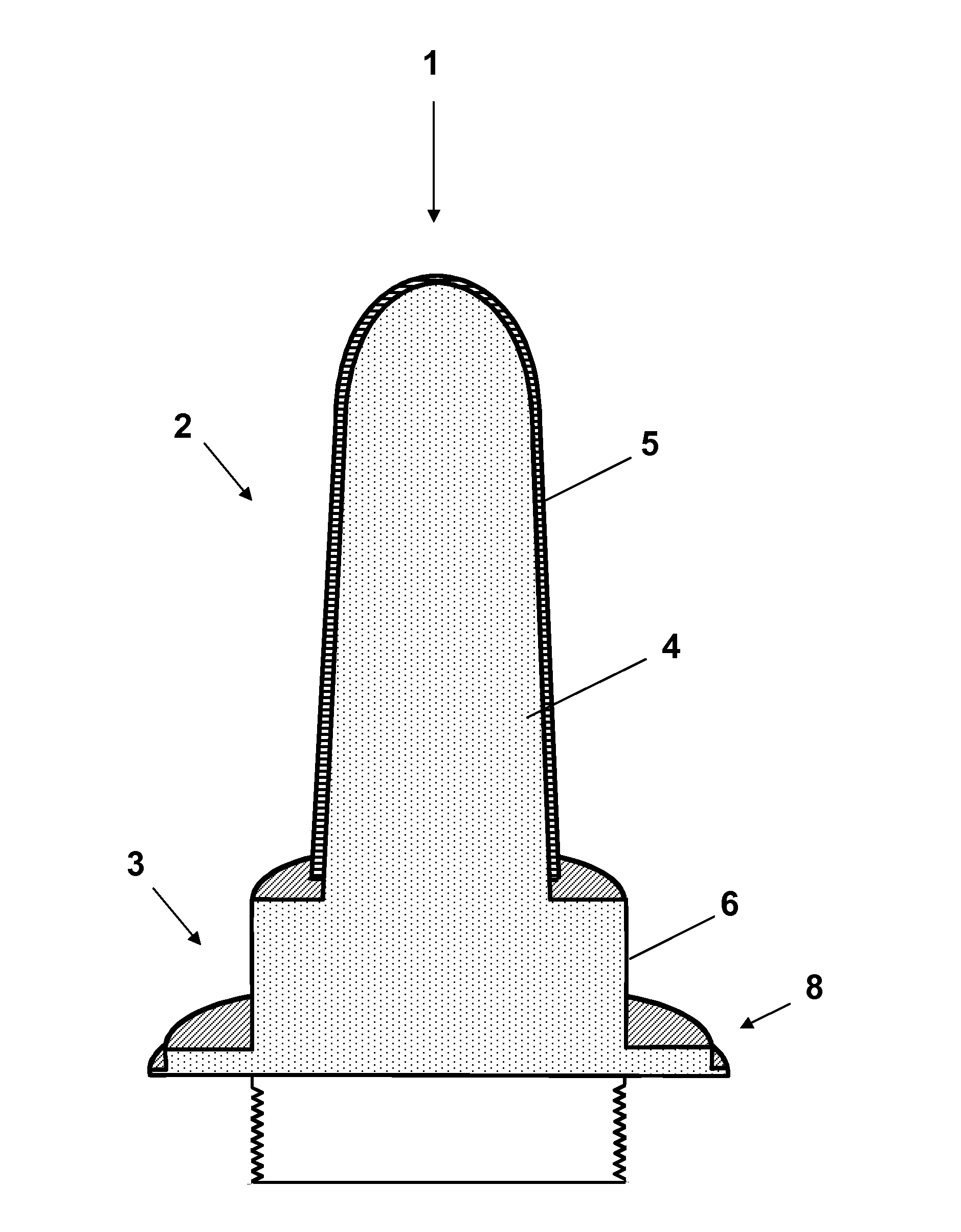
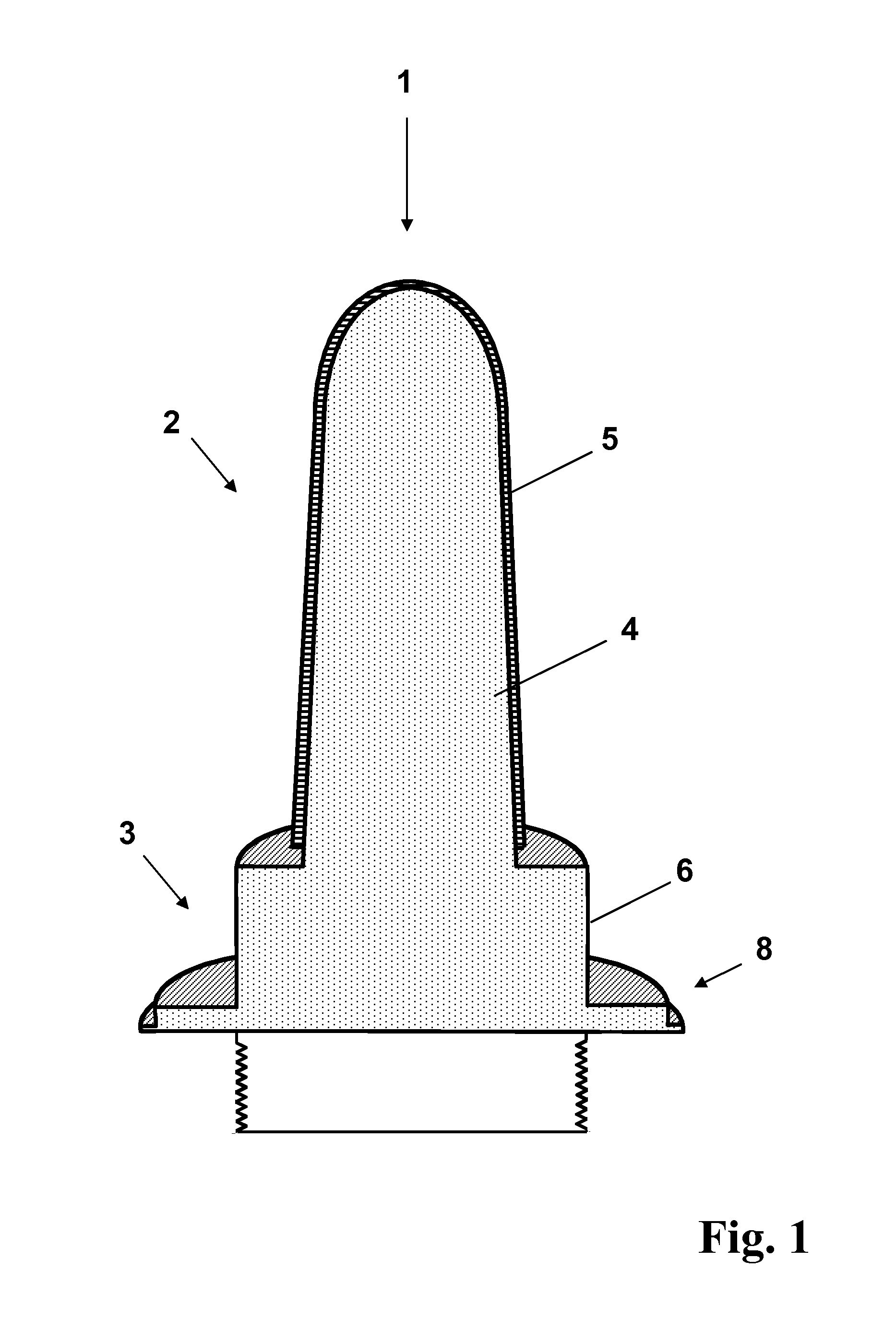
Plunger for use in manufacturing glass containers
a technology for glass containers and pluggers, which is applied in the field of automatic production of glass containers, can solve the problems of high production costs, high production costs, and high production costs, and achieve the effects of improving wear, corrosion and thermal fatigue resistance, and easy production and cost-effectiveness
- Summary
- Abstract
- Description
- Claims
- Application Information
AI Technical Summary
Benefits of technology
Problems solved by technology
Method used
Image

Examples
example
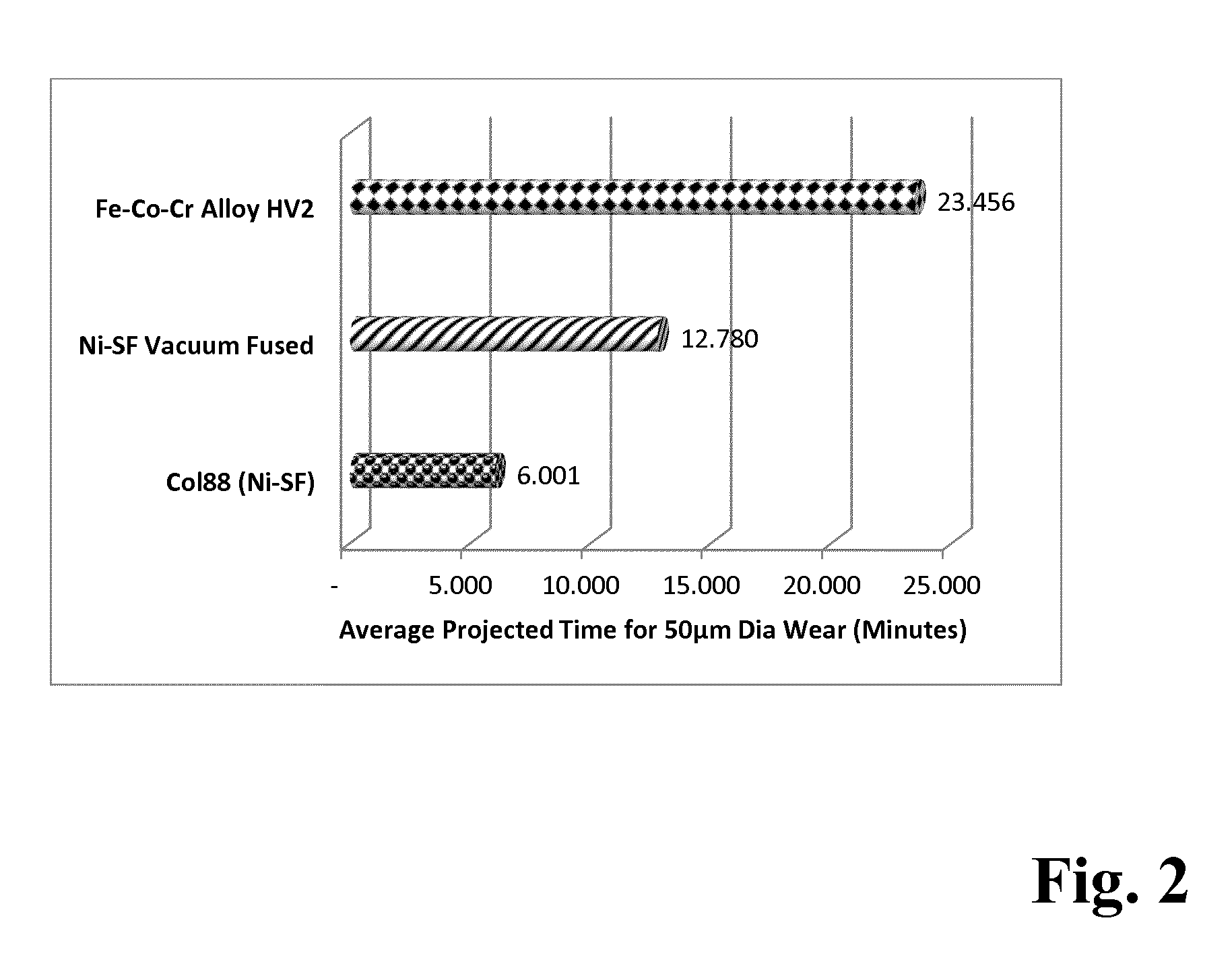
[0050]A Fe-based alloy having the composition as shown in Table 1 was atomized and formed into a powder with a mean particle size of 100 μm.
TABLE 1(HV2)C 1.5 wt. %Si 2.0 wt. %B3.0 wt %Cr21.5 wt % Ni3.5 wt %Co30.0 wt % W2.0 wt %FeBalance
[0051]The powder is deposited as a layer on the plunger nose surface using a High Velocity Oxygen Fuel (HVOF) thermal spray process. Subsequently, the sprayed layer is fused by induction fusion at 1,100° C. The mean thickness of the layer obtained is approximately 1 mm. In order to avoid cracks the fused layer is cooled down slowly. It has a mean microhardness of 457 HV0.3.
[0052]In an alternative embodiment of the present invention, instead of induction fusion other heating processes, e.g. by flame or in an oven, is used.
[0053]In addition, only the layer at the shank and the tip are again manually fused by flame assisted melting. Finally, the plunger nose surface is machined and polished. In an alternative embodiment, the alloy shown in table 1...
PUM
| Property | Measurement | Unit |
|---|---|---|
| thickness | aaaaa | aaaaa |
| thickness | aaaaa | aaaaa |
| temperature | aaaaa | aaaaa |
Abstract
Description
Claims
Application Information
 - R&D
- Intellectual Property
- Life Sciences
- Materials
- Tech Scout
- Unparalleled Data Quality
- Higher Quality Content
- 60% Fewer Hallucinations
Browse by: Latest US Patents, China's latest patents, Technical Efficacy Thesaurus, Application Domain, Technology Topic, Popular Technical Reports.
© 2025 PatSnap. All rights reserved.Legal|Privacy policy|Modern Slavery Act Transparency Statement|Sitemap|About US| Contact US: help@patsnap.com