
Plasma processing apparatus

a processing apparatus and plasma technology, applied in the direction of electrical apparatus, plasma technique, electric discharge tubes, etc., can solve the problems of difficult control of etching depth and damage to gate oxide films, and achieve stable and accurate matching operation and high reproducibility

Active Publication Date: 2015-01-01
TOKYO ELECTRON LTD +1
View PDF13 Cites 24 Cited by
  • Summary
  • Abstract
  • Description
  • Claims
  • Application Information

AI Technical Summary

Benefits of technology

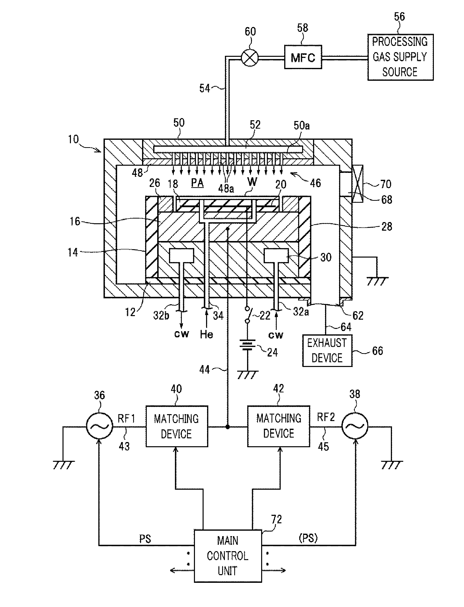
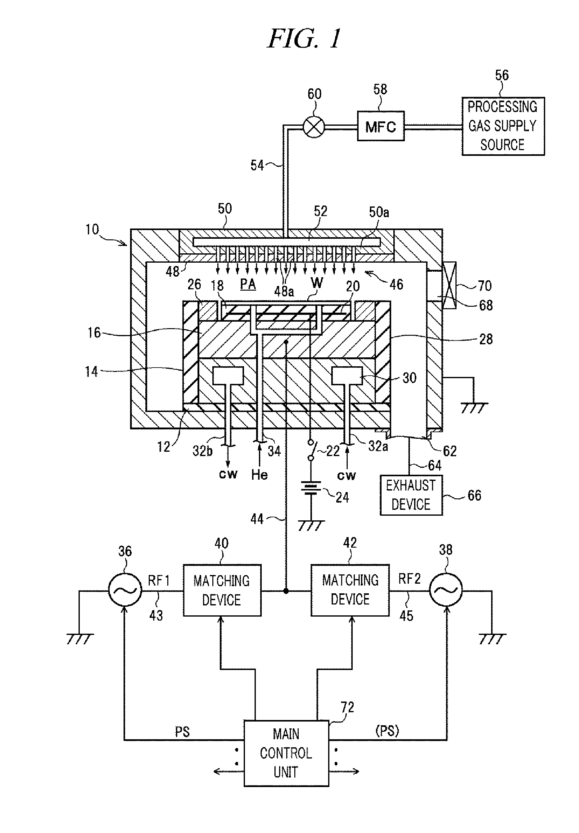
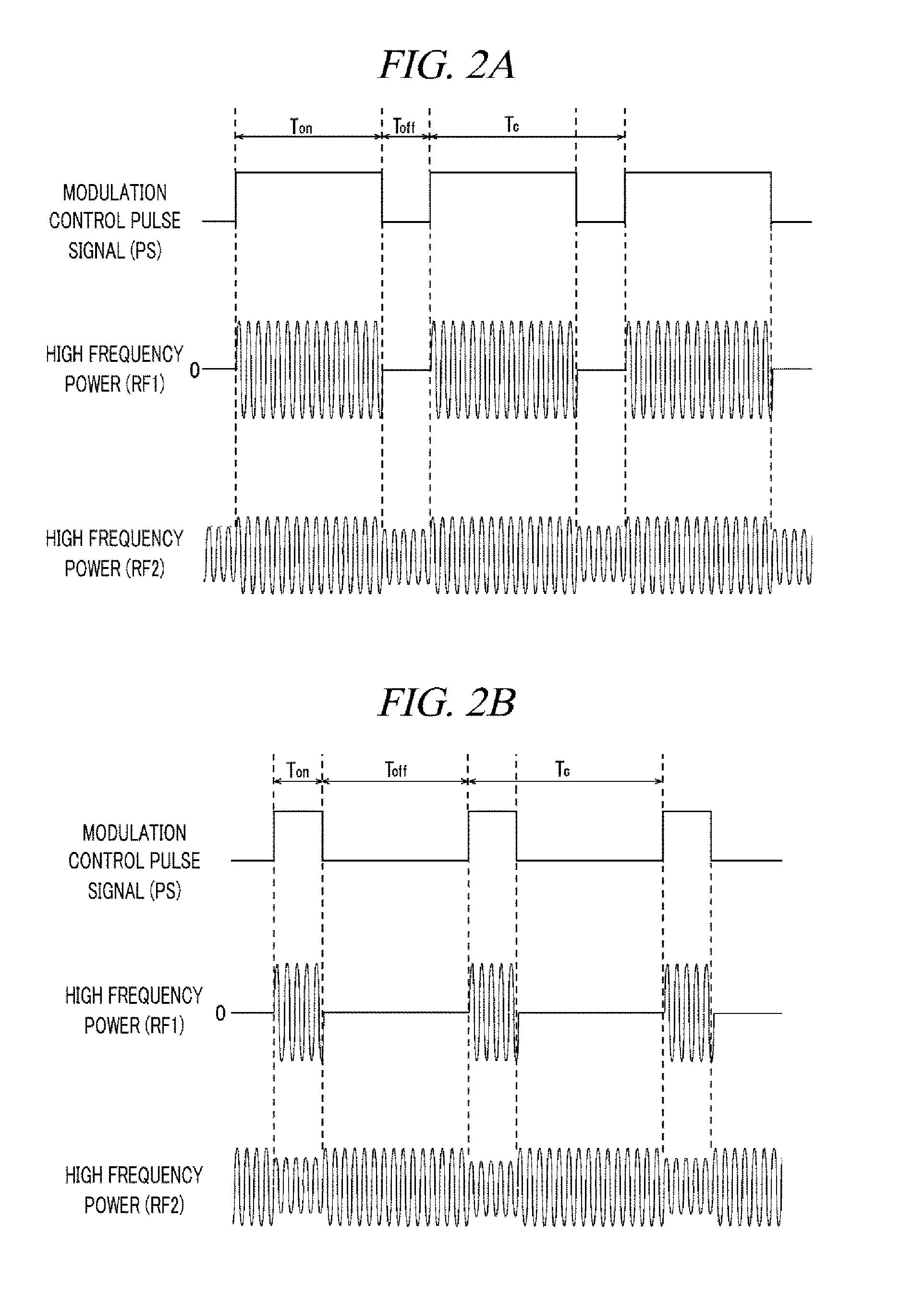
The patent describes a plasma processing apparatus that can accurately match the high frequency power supplied to a processing vessel in a pulse shape. This results in a high reproducibility of the plasma processing.

Problems solved by technology

However, if the ion energy is lowered at a lower pressure, the non-uniformity of the plasma potential in the entire surface of the substrate may easily cause the charging damage on a gate oxide film.
That is, an etching rate may differ depending on the hole size, so that it is difficult to control an etching depth.

Method used


Image

  • Plasma processing apparatus
  • Plasma processing apparatus
  • Plasma processing apparatus

Examples


example embodiment or modification example

Another Example Embodiment or Modification Example

[0117]The preferable example embodiment has been explained, but the present disclosure is not limited to the above example embodiment and can be modified in various ways within a technical scope thereof.

[0118]By way of example, as depicted in FIG. 13, the impedance sensor 96A within the matching device 40 may include the RF voltage detector 100A, the RF electric current detector 108A, a load impedance calculating circuit 120A, a sampling-average-value calculating circuit 122A, and a moving-average-value calculating circuit 124A.

[0119]Herein, the load impedance calculating circuit 120A is configured to calculate a measurement value of load impedance on the high frequency transmission line 43 based on the RF voltage detection signals and the RF electric current detection signals obtained from the RF voltage detector 100A and the RF electric current detector 108A, respectively. The load impedance calculating circuit 120A may be an analo...


PUM

PropertyMeasurementUnit
frequencyaaaaaaaaaa
frequencyaaaaaaaaaa
frequencyaaaaaaaaaa

Abstract

A plasma processing apparatus performs a stable and accurate matching operation with high reproducibility in a power modulation process of modulating of a high frequency power to be supplied into a processing vessel in a pulse shape. In the plasma processing apparatus, an impedance sensor 96A provided in a matching device performs a dual sampling averaging process on a RF voltage measurement value and an electric current measurement value respectively obtained from a RF voltage detector 100A of a voltage sensor system and a RF electric current detector 108A of an electric current sensor system by sampling-average-value calculating circuits 104A and 112A and by moving-average-value calculating circuits 106A and 114A. Thus, an update speed of a load impedance measurement value outputted from the impedance sensor 96A can be matched well with a driving control speed of a motor in a matching controller.

Description

TECHNICAL FIELD[0001]The embodiments described herein pertain generally to a technique of performing a plasma process on a processing target substrate, and particularly, to a capacitively coupled plasma processing apparatus in which a high frequency power to be supplied into a processing vessel is modulated in a pulse shape.BACKGROUND[0002]A capacitively coupled plasma processing apparatus includes an upper electrode and a lower electrode arranged in parallel to each other within a processing vessel. A processing target substrate (e.g., a semiconductor wafer, a glass substrate, etc) is mounted on the lower electrode, and a high frequency power having a frequency (typically, about 13.56 MHz or higher) suitable for plasma generation is applied to the upper electrode or the lower electrode. Electrons are accelerated by a high frequency field generated between the two facing electrodes by applying the high frequency power, and plasma is generated as a result of ionization by collision b...

Claims


Application Information

Patent Timeline
Patent Type & Authority Applications(United States)
IPC IPC(8): H01J37/32
CPCH01J37/32183H01J2237/334H01J2237/24564H01J2237/24495H05H2001/4682H01J37/32146H05H1/46H01J37/32165H01J37/32091H05H2242/26
Inventor YAMADA, NORIKAZUTACHIKAWA, TOSHIFUMINAGAMI, KOICHIHAMAISHI, SATORUITADANI, KOJI
Owner TOKYO ELECTRON LTD
Learn More