
Heating device for rotary drum freeze-dryer

a technology of heating device and freeze-dryer, which is applied in the direction of drying machines, lighting and heating apparatus, furniture, etc., can solve the problems of reducing drying efficiency, limited maximum temperature of heated walls, and prolonging freeze-drying process, so as to minimize required wall thickness, optimize mechanical stability, and simplify freeze-dryer design

Active Publication Date: 2015-01-08
SANOFI PASTEUR SA
View PDF13 Cites 9 Cited by
  • Summary
  • Abstract
  • Description
  • Claims
  • Application Information

AI Technical Summary

Benefits of technology

The present invention aims to provide an improved heating device for a rotary drum based freeze-dryer that allows for efficient cleaning and / or sterilization, and prevents any kind of leakage. This device enables effective implementation of Cleaning in Place (“CiP”) and / or Sterilization in Place (“SiP”) concepts, and ensures high product quality without occurrence of partially or totally melted (molten) product. Additionally, it allows for shorter drying times than are currently achievable, increasing the applicability of rotary drum based freeze-drying.

Problems solved by technology

However, ongoing sublimation in the process volume tends to decrease the temperature further, which leads to a decrease in drying efficiency.
As a result, the maximum temperature of the heated wall is limited to a value where the product quality is not negatively affected, e.g., due to partial or total melting of the particles stuck thereto.
This generally limits the proposition of heat transfer via the inner wall surface of a rotary drum and consequently lengthens the freeze-drying process since it is difficult to maintain the optimum drying temperature in the absence of other heating mechanisms.
However, such a heating source can negatively affect product quality.
This can lead to a fraction of the product being partially or totally melted.
As a result, product quality can be negatively affected, and problems with operating the emitter can occur, and / or problems with subsequent cleaning and / or sterilization processes can occur.
Furthermore, due to the different coefficients of thermal expansion inherent in the different construction materials typically used in the drums and emitter devices gaps can develop between components.
This is particularly an issue when typical infrared emitters are used under vacuum process conditions inside the drum.
Also, infrared heating sources are particularly difficult to clean or sterilize due to the mix of materials and the use of gaskets between components such as flanges and glass tubes.

Method used


Image

  • Heating device for rotary drum freeze-dryer
  • Heating device for rotary drum freeze-dryer
  • Heating device for rotary drum freeze-dryer

Examples


Embodiment Construction

AND PREFERRED EMBODIMENTS

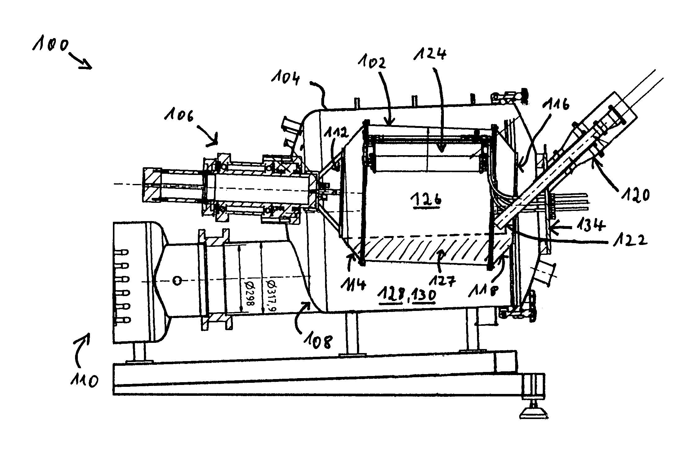
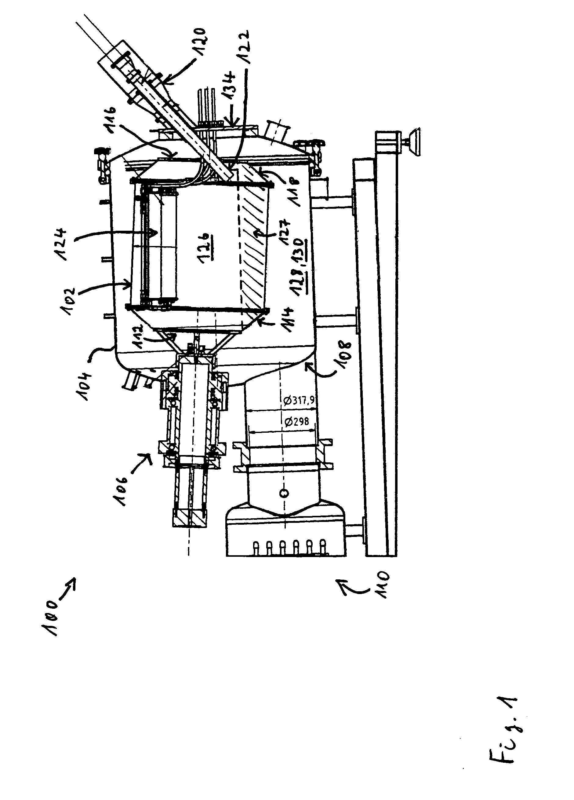
[0104]FIG. 1 schematically illustrates in a cross-sectional view an explanatory example 100 of a freeze-dryer comprising a rotary drum 102 supported within a housing chamber 104 by a single rotary support 106. The housing chamber 104 is implemented as a vacuum chamber and connected via opening 108 with condenser and vacuum pump 110. The freeze-dryer 100 is adapted for freeze-drying particles such as microparticles, preferably micropellets, under closed conditions, i.e. under conditions of sterility and / or containment.

[0105]Drum 102 comprises an opening 112 on its rear plate 114 and an opening 116 on its front plate 118. Opening 116 is adapted for loading the drum 102 with particles via a transfer section 120 comprising an interior guiding tube 122 for guiding a product flow from an upstream particle storage / container and / or particle generation device (such as a spray chamber, prilling tower, and the like) into drum 102.

[0106]The drum 102 comprises a heating ...


PUM


Abstract

A heating device (124) for heating particles to be freeze-dried in a rotary drum (102) of a freeze-dryer (100) is provided, the device comprising at least one radiation emitter (202) for applying radiation heat to the particles, and a tube-shaped separator (204) for separating the particles from the at least one emitter (202). The separator (202) being integrally closed at one end and separating an emitter volume (206) encompassing the at least one emitter (202) from a drum process volume (126) inside the drum (102), wherein the heating device (124) protrudes into the drum process volume (126) such that said integrally closed end of the separator (204) is arranged inside the drum (102) as a free end.

Description

TECHNICAL FIELD[0001]The invention relates to a heating device for heating particles to be freeze-dried in a drying device (e.g., a rotary drum) of a freeze-dryer or freeze-drying process line, to a separator thereof, as well as to a wall section of corresponding devices in a freeze-dryer or freeze drying process line.BACKGROUND OF THE INVENTION[0002]Freeze-drying, also known as lyophilization, is a process for drying high-quality products such as, for example, pharmaceuticals, biological materials such as proteins, enzymes, microorganisms, and in general any thermo- and / or hydrolysis-sensitive materials. Freeze-drying provides for the drying of the target product via sublimation of ice crystals into water vapor, i.e., via the direct transition of at least a portion of the water content of the product from the solid phase into the gas phase.[0003]Freeze-drying processes in the pharmaceutical area can be employed, for example, for the drying of drugs, drug formulations, Active Pharma...

Claims


Application Information

Patent Timeline
Patent Type & Authority Applications(United States)
IPC IPC(8): F26B3/30F26B5/06F26B11/02
CPCF26B3/30F26B11/026F26B5/06
Inventor GEBHARD, THOMASKASIER, ROLANDPLITZKO, MATTHIASSTRUSCHKA, MANFREDLUY, BERNHARD
Owner SANOFI PASTEUR SA
Learn More