Continuous fixed-bed catalytic reactor and catalytic reaction method using same

a technology of fixed-bed catalytic reactor and catalytic reaction method, which is applied in the direction of combustible gas catalytic treatment, physical/chemical process catalysts, combustible gas purification/modification, etc., can solve the problem of affecting the operation efficiency of the catalytic reactor, the catalytic layer becomes blocked, and the operation is also likely to become unstable, so as to achieve efficient removal of solid accumulated substances and high efficiency

Active Publication Date: 2015-01-08
NIPPON STEEL CORP
View PDF2 Cites 62 Cited by
  • Summary
  • Abstract
  • Description
  • Claims
  • Application Information

AI Technical Summary

Benefits of technology

[0045]According to the continuous fixed-bed catalytic reactor of the invention, it is possible to efficiently remove a solid accumulated substance which is generated and accumulated on the catalyst particles in the fixed-bed catalyst layer so as to degrade the catalyst performance and causes the blockage in the catalyst layer by moving the entire catalyst layer up and down. Therefore, it is not necessary to stop the operation to wash the blocked catalyst holder as in the related art, and it becomes possible to continuously operate the reactor. In addition, it is possible to cause with a high efficiency a catalytic reaction generating a solid product such as solid carbon using the continuous fixed-bed catalytic reactor.

Problems solved by technology

Therefore, a problem of the catalyst layer becoming blocked and thus incapable of ventilating is caused.
However, compared with the fixed-bed catalytic reaction container, the above-described containers are complex, and the operation is also likely to become unstable in the fluidized-bed catalytic reaction container.
Therefore, the above-described containers are not ordinary as a reaction container particularly for treating a highly corrosive high-temperature and high-pressure fluid.
However, in this case, it is not possible to prevent the blockage in the catalyst layer caused by dust that is generated in the catalyst layer, is attached to and accumulates on the catalyst in the space between the catalyst particles.
Therefore, while this technique is effective for a relatively small catalyst layer like a catalyst layer in a cell for a fuel battery, in a large catalyst layer treating a large amount of a fluid, it is difficult to vibrate the entire catalyst layer using an ultrasonic wave.
Therefore, a decrease in the catalytic reaction temperature hinders the catalytic reaction from occurring under the optimal condition, and therefore there is a problem of the degradation of catalyst performance.
In this case, there is a problem in that hammering or vibration increases the filling rate of a catalyst so as to narrow spaces between catalyst particles, and conversely, the fluidity of the catalyst deteriorates.
All of the catalytic reaction containers are provided with catalyst layers and exclusive airflow paths surrounded by the catalyst layers, thereby reducing the airflow resistance in the catalytic reaction containers.
Alternatively, even in a case in which the airflow paths are not blocked, the exchange of a fluid between the exclusive airflow paths and the catalyst layers is hindered by the solid product accumulated on the catalyst surface configuring the exclusive airflow paths, and therefore a “blow-by” phenomenon is caused in which raw material gas is drained without coming into contact with the active catalyst so as to significantly decrease the catalytic reaction efficiency.
Conversely, in the case of an exothermic reaction in which the catalytic reaction is intensive, it is not possible to emit the generated heat to the outside through the reaction container at portions deep inside the reaction container, and thus the fluid temperature excessively increases on the downstream side such that the catalyst is inactivated, and in some cases, the catalytic reaction container is burned out.
Furthermore, in the case of the monolith-type reaction container, it is necessary to mold an entire monolith which generally has a complex shape and a large size as a carrier for carrying the catalyst or a single structure of the catalyst, and thus there is a problem in that the applicable catalyst design (structure) is limited to a relatively simple design (for example, a design in which a catalyst containing a single chemical component is uniformly applied to a carrier surface, or the like) due to catalyst-manufacturing techniques.
Therefore, it is significantly difficult to apply the monolith-type reaction container to a catalyst having a complex design (structure) in which the surface is finely divided into a plurality of compartments of different chemical components and the respective chemical components exhibit a catalytic effect in mutual cooperation like, for example, a tar-reformed catalyst, and, even when such application is possible, the application becomes extremely expensive.

Method used


Image

  • Continuous fixed-bed catalytic reactor and catalytic reaction method using same
  • Continuous fixed-bed catalytic reactor and catalytic reaction method using same
  • Continuous fixed-bed catalytic reactor and catalytic reaction method using same

Examples


third embodiments

First to Third Embodiments

[0137]First to third embodiments of the invention will be described in detail with reference to the accompanying drawings. Meanwhile, in the following description and drawings, components having substantially the same function will be provided with the same reference signs, and the duplicate description thereof will not be made.

first embodiment

Overall Structure

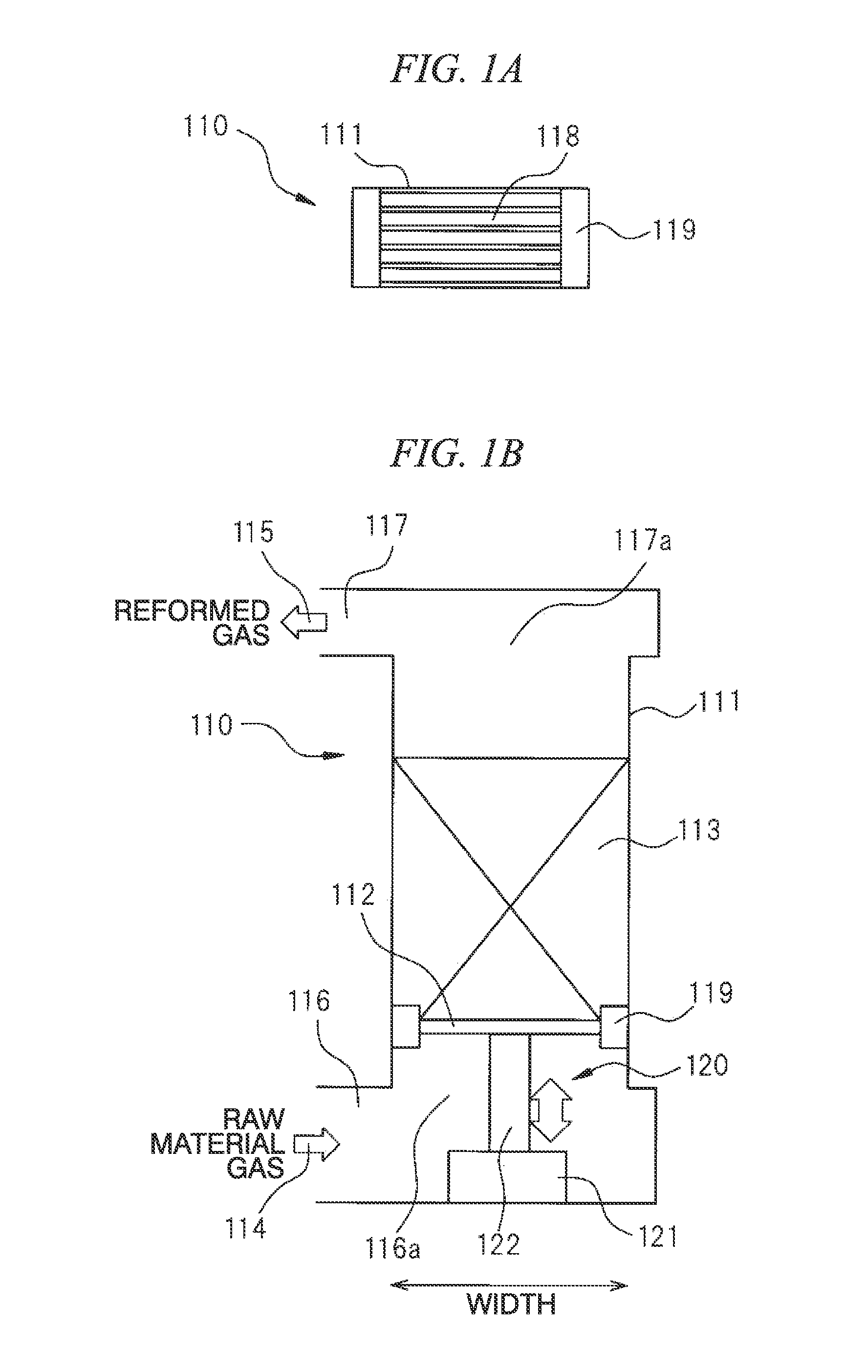
[0138]FIGS. 1A, 1B and 1C illustrate a continuous fixed-bed catalytic reactor 110 according to a first embodiment of the invention. FIG. 1A is a plan view, FIG. 1B is a front view, and FIG. 1C is a side view. The continuous fixed-bed catalytic reactor 110 of the embodiment includes a reaction container 111. The reaction container 111 accommodates a catalyst layer 113 which is a group of clumpy catalyst particles and is supported by a holder 112 having a ventilation property at the bottom section. Among catalyst particles in the catalyst layer 113, catalyst particles adjacent to the inner wall of the reaction container (not illustrated) are in contact with the inner wall of the reaction container. In the embodiment, since the catalyst layer is moved up and down by bringing the catalyst particles into contact with the inner wall of the reaction container, the inner surface of the reaction container 111 is preferably planar so as to prevent the hindrance of the movemen...

second embodiment

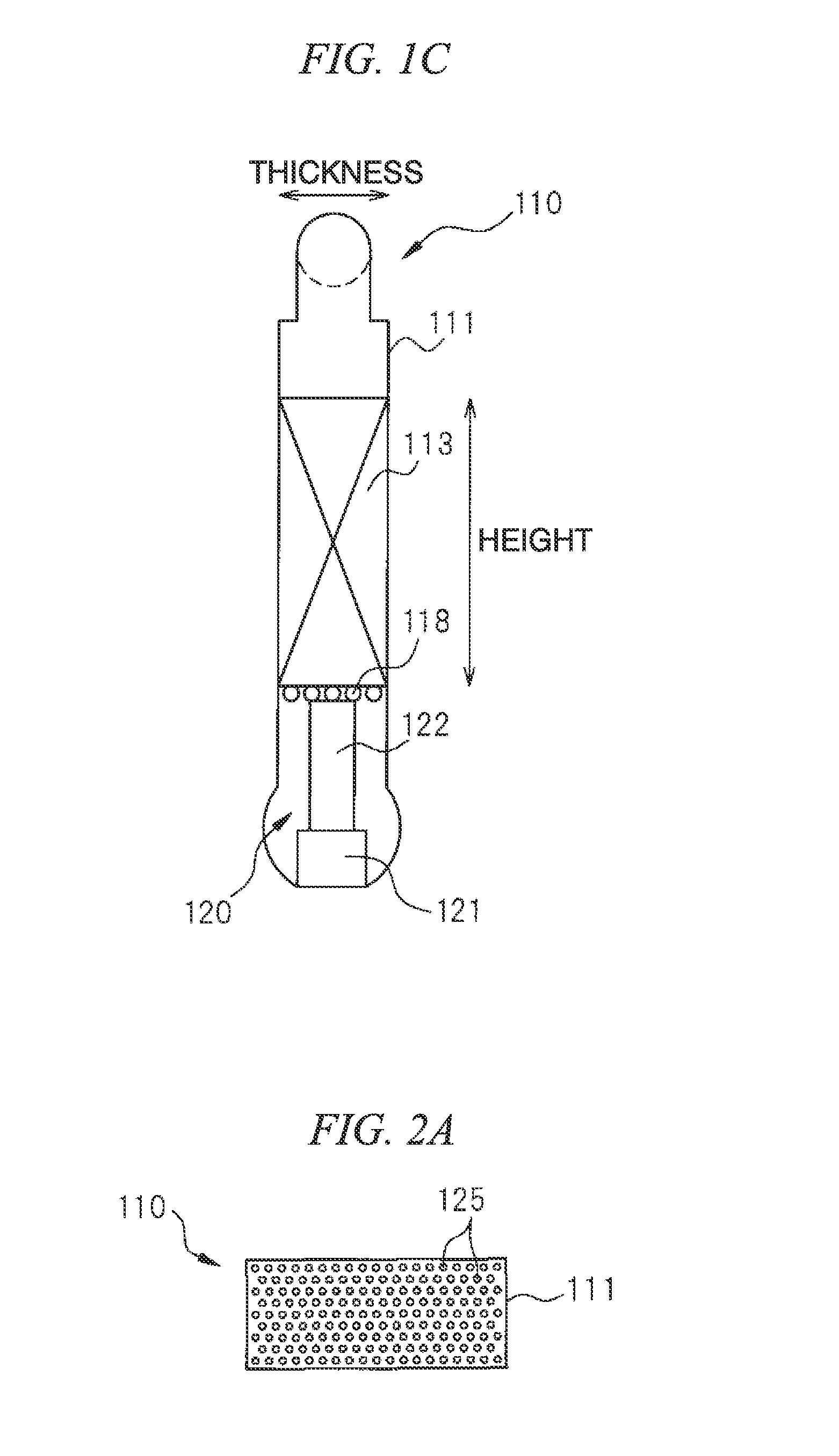
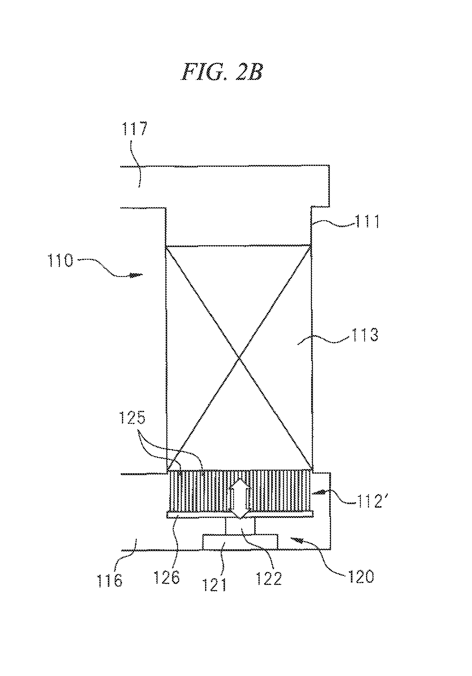
[0185]Next, a continuous fixed-bed catalytic reactor according to a second embodiment will be described with reference to FIGS. 2A, 2B and 2C. FIG. 2A is a plan view, FIG. 213 is a front view, and FIG. 2C is a side view. A continuous fixed-bed catalytic reactor 110 of FIGS. 2A, 2B and 2C is the same as the continuous fixed-bed catalytic reactor of the first embodiment described with reference to FIGS. 1A, 1B and 1C except for the fact that a number of pins are used in a catalyst holder as illustrated in FIG. 7.

[0186]In the present embodiment, the reaction container 111 includes a catalyst holder 112′ at a bottom section which is an inflow opening to the reaction container 111. The catalyst holder 112′ is a structure having a number of pins 125 held in a bottom plate 126, and is a catalyst-holding unit that directly holds a clumpy catalyst in the catalyst layer 113 at the front end sections of the pins 125. When the pins 125 are provided at intervals that are smaller than the size of...


PUM

PropertyMeasurementUnit
diameteraaaaaaaaaa
heightaaaaaaaaaa
thicknessaaaaaaaaaa

Abstract

A continuous fixed-bed catalytic reactor includes an inflow path for raw material gas for a catalytic reaction and an outflow path for reformed gas, a catalytic reaction container that is connected to the inflow path and the outflow path and holds a clumpy catalyst, catalyst holders that have a ventilation property and hold the clumpy catalyst, and a driving mechanism that moves the clumpy catalyst up and down by moving the catalyst holders up and down.

Description

TECHNICAL FIELD OF THE INVENTION[0001]The present invention relates to a continuous fixed-bed catalytic reactor for causing a chemical reaction of a fluid using a clumpy catalyst and a technique for a catalystic reaction method using the same.[0002]Priority is claimed on Japanese Patent Application No. 2012-010460, filed Jan. 20, 2012, Japanese Patent Application No. 2012-010464, filed Jan. 20, 2012, and Japanese Patent Application No. 2012-010479, filed Jan. 20, 2012, the contents of which are incorporated herein by reference.RELATED ART[0003]In a chemical reaction of a fluid using a fixed-bed catalytic reaction container filled with a catalyst, in a case in which a solid precipitate or the like is generated due to a catalytic reaction, the solid precipitate frequently accumulates in spaces between catalyst particles in a catalyst layer. Therefore, a problem of the catalyst layer becoming blocked and thus incapable of ventilating is caused.[0004]For example, Patent Document 1 discl...

Claims


Application Information

Patent Timeline
Patent Type & Authority Applications(United States)
IPC IPC(8): B01J8/02C01B3/02
CPCB01J8/02C01B3/02B01J8/0285B01J8/008B01J8/0242B01J8/0278B01J8/06B01J8/08B01J8/16B01J12/007B01J15/005B01J19/249B01J19/32B01J21/066B01J23/83B01J35/023B01J35/026B01J37/0036B01J37/03B01J2208/00849B01J2208/00858B01J2208/00884B01J2208/00929B01J2208/00938B01J2208/023B01J2219/00247B01J2219/30223B01J2219/30408B01J2219/30416B01J2219/30475B01J2219/3085B01J2219/32279B01J2219/32282B01J2219/32286B01J2219/32466C10G49/002C10K1/34C10K3/02C10K3/023
Inventor ITO, NOBUAKISUZUKI, KIMIHITOFUJIMOTO, KENICHIRONAKAO, KENJI
Owner NIPPON STEEL CORP
Why Eureka
Try Eureka