Graphene Nanoribbons and Methods
a graphene nanoribbon and nanotube technology, applied in the field of graphene nanoribbons and methods, can solve the problems of difficult positioning of gnrs as desired, device fabrication process,
- Summary
- Abstract
- Description
- Claims
- Application Information
AI Technical Summary
Benefits of technology
Problems solved by technology
Method used
Image

Examples
example 1
Prepare CNT Film and Laser Irradiation
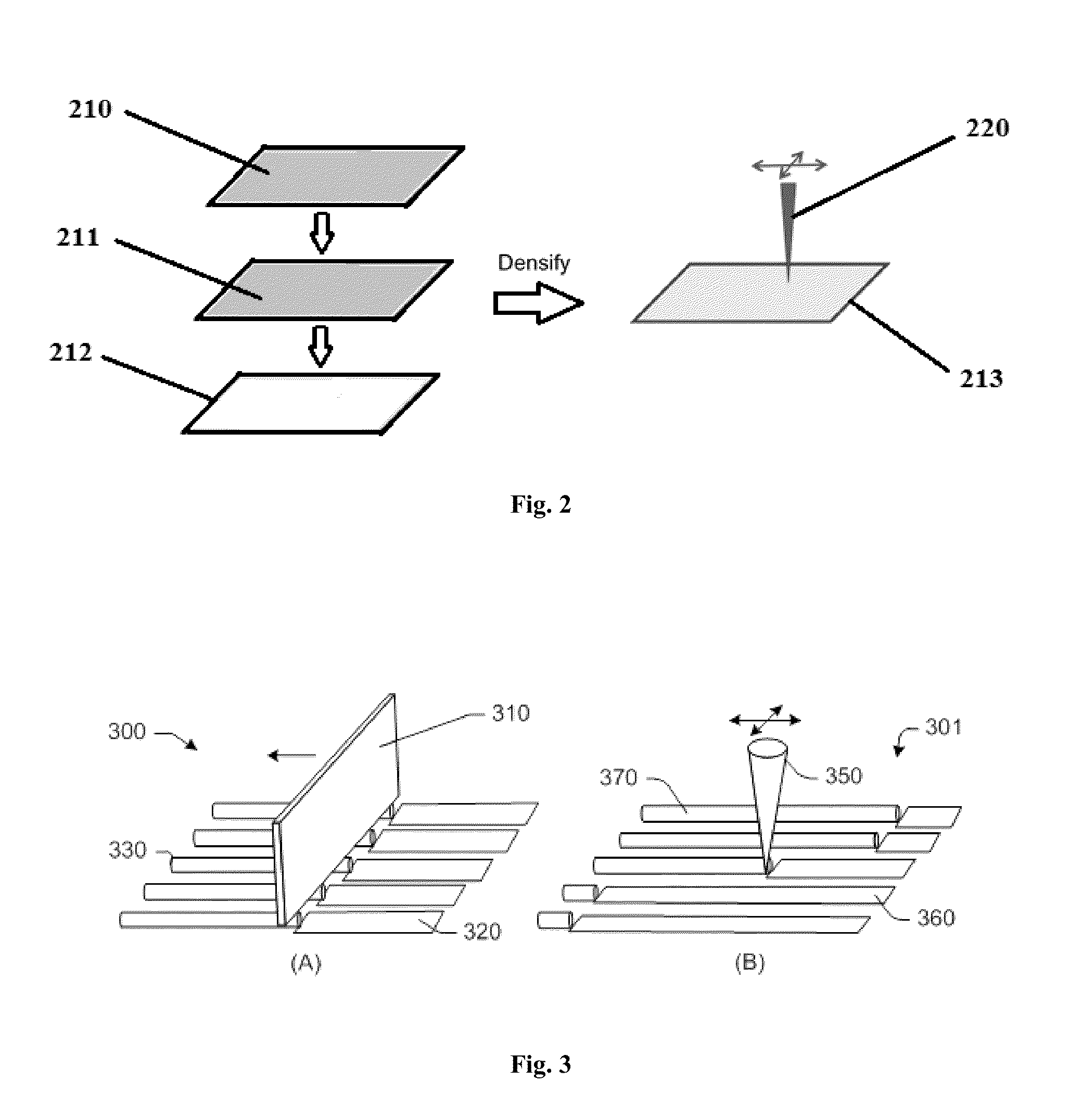
[0037]A schematic illustration of preparing a CNT film and the laser irradiation process, according to one embodiment, is shown at FIG. 2. Two freestanding CNT sheets (210, 211) of substantially aligned CNTs were transferred to a frame 212, densified, and the framed sheets 213 were irradiated by a laser 220. In FIG. 2, the two CNT sheets (210, 211) were stacked so that the substantially aligned CNTs of each sheet were oriented in the same direction. In other embodiments, however, two or more CNT sheets can be stacked together so that the substantially aligned CNTs of each sheet have different orientations relative to each other.
[0038]FIG. 3 includes schematic illustrations (300, 301) of the laser irradiation of a CNT film according to one embodiment. The scanning pattern is related to the shape of the laser. FIGS. 3A and 3B show the scan using a laser line 310 and laser spot 350, respectively. The parameters of the scan, such as the scan directi...
example 2
Unzipping CNTs by CO2 Laser to Form GNRs and GNR Network
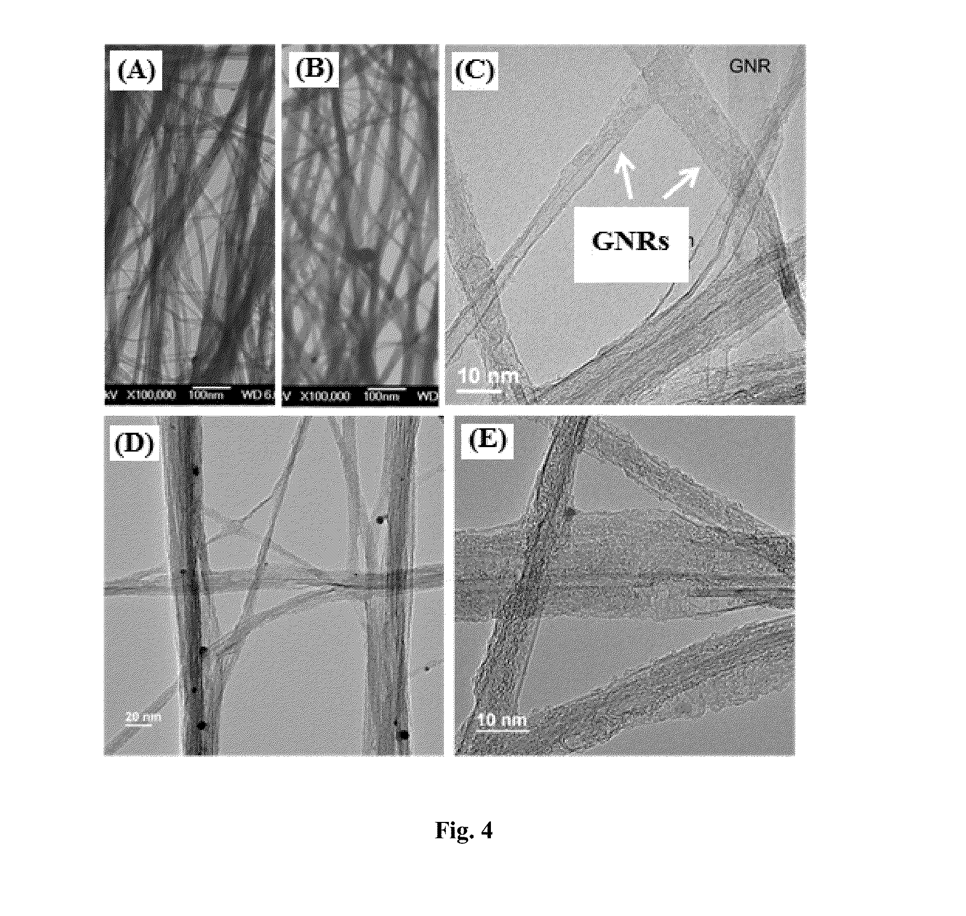
[0039]FIG. 4 shows the high-resolution transmission electron microscopy (TEM) images of the CNT film and the GNRs formed by laser unzipping CNTs in one embodiment. The CNT film was formed by stacking 4 layers of CNT sheets on a frame with ±5 degree offset in orientation, and then densifying the layers by immersing in isopropanol (IPA) and drying in air.
[0040]A standard, computer controlled laser instrument was used. The laser was a CW CO2 laser with 10.6 μm wavelength and 0.5 W power. The diameter of the focused laser spot on CNT film was 80 μm. The laser was perpendicularly applied to the surface of the CNT film and swept on the suspended CNT film. The power density of the laser was 9.9 kW / cm2. The line density of the beam spot was set at 150 points / cm, and the laser irradiation was performed in air with the scan speed of 15 cm / s.
[0041]FIGS. 4A and 4B show the TEM images of the CNTs before and after laser irradiation, respecti...
example 3
Large-Scale Manufacturing Process
[0043]Some of the processes described herein are batch processes, but, in embodiments, the processes can be operated in a continuous fashion or be developed into roll-to-roll processes.
[0044]A continuous process is illustrated in FIG. 5A. The freestanding CNT sheet 510 is formed by drawing CNTs from a CNT forest 511 grown on a substrate 512, the CNT sheet 510 is converted into a GNR network 513 by spot laser irradiation 514 to unzip the CNTs, then the GNR network 513 is transferred to a flexible film 519 drawn from a film roll 515 to produce a GNR network on a film 516. A reflector 519 is positioned under the laser irradiation 514. Adhesion to the film is then reinforced by the capillary force introduced during the drying of the sprayed solvent 517 or further laser treatment (not shown). The GNR network on a film 516 is then be collected on a roll 518.
[0045]FIG. 5B illustrates a process for making large size electrode. The CNT sheet 550 drawn from a ...
PUM
| Property | Measurement | Unit |
|---|---|---|
| thickness | aaaaa | aaaaa |
| angle | aaaaa | aaaaa |
| thickness | aaaaa | aaaaa |
Abstract
Description
Claims
Application Information