Pressure infusion lining system

a technology of pressure infusion and lining system, which is applied in the direction of coatings, mechanical equipment, other domestic objects, etc., can solve the problems of pipeline deterioration, pipeline deterioration, holes, cracks, etc., and achieve the effect of effectively sealing all cracks and faults, sacrificing the integrity of sealing

Inactive Publication Date: 2015-01-22
WARREN ENVIRONMENTAL & COATING LLC
View PDF8 Cites 40 Cited by
  • Summary
  • Abstract
  • Description
  • Claims
  • Application Information

AI Technical Summary

Benefits of technology

[0018]A new pipe within a pipe is thereby created by using potable water approved resins that can be cured under water with strong adhesion properties to wet under water substrates combined with woven structural fabrics such as carbon fiber and S glass structural fiberglass woven together. This process will make the host pipe 100 times plus stronger than it was when it was new, and stronger than any new pipe line product other than stainless steel or carbon steel pipe. The infusion liner will completely protect the water flowing within the pipe from free release into the water flow of any asbestos, lead PBCs or PVCs, and any surface ground water pollutants that may have previously entered through open pipe joints, cracks or breaks caused by the Venturi effect of flowing water.
[0019]This invention eliminates the need for wet out facilities, over the road transport of materials, and the need for steam or boiler trucks.
[0020]Therefore, it is an object of the present invention to provide a new and novel process for lining the interior surface of a pipeline to repair and salvage the pipe so that is can be used normally in a leak-free condition. It is another object of the invention to provide a structural lining process that effectively seals all cracks and faults in an existing pipeline. A further object of the invention is to provide a structural lining process that installs a sealing inner liner that is well suited to seal corner joints within a pipeline. A further object of the present invention is to provide a structural lining process that relatively inexpensive to carry out compared to prior art processes without sacrificing the integrity of the sealing and repair accomplished by the process of the present invention.

Problems solved by technology

Since these pipelines are installed underground, they are constantly subjected to numerous environmental pressured that cause the pipeline to deteriorate.
For example, the pipeline may deteriorate due to ordinary aging, corrosive action of the fluids being transported in the line, environmental conditions such as groundwater exposure, or other reasons.
Over time, all of the wear factors that impact on the pipeline result in holes, cracks, and other defects in the line that must be repaired in order to prevent fluid leakage problems.
In some instances, the concern is that foreign matter, which is initially part of the actual construction of the pipeline, may begin to flake off of the interior surfaces of the damaged pipeline and enter the fluid flow within the pipeline.
For example, ductile iron piping has a clay liner surface that upon failure may allow rust to enter the fluid flow.
Finally, the potential exists for the introduction of substances that flow from the surrounding underground environment into the pipeline or for the water that is being carried through the pipeline conduit to flow outwardly through the cracks leading to a loss of water pressure and other problems.
Given the millions of miles of installed pipeline in the United States alone, this solution would be prohibitively expensive.
Further, such pipelines are typically located beneath streets and right of ways where digging would create traffic flow problems and require extensive repaving of roadways as the replacement process was completed.
Although the above-described conventional methods may be somewhat effective in repairing pipelines, they still suffer from various problems.
For example, problems arise concerning the inversion of a felt liner because it is relatively delicate and tends to break or rip during the inversion process.
Also, pulling prior art liner tubes around corners is very difficult resulting in fractures in the sealing at such joints.
Also, the pipeline joints found at corners and periodically along the length of the pipeline forms voids that cannot be completely filled by the prior art methods.
Thus, the prior art methods can do nothing to improve the strength of the pipeline at its joints.
Another difficulty is that once a liner has been installed, the identification of lateral supply pipe branches are difficult to identify and clear.

Method used


Image

  • Pressure infusion lining system
  • Pressure infusion lining system
  • Pressure infusion lining system

Examples


Embodiment Construction

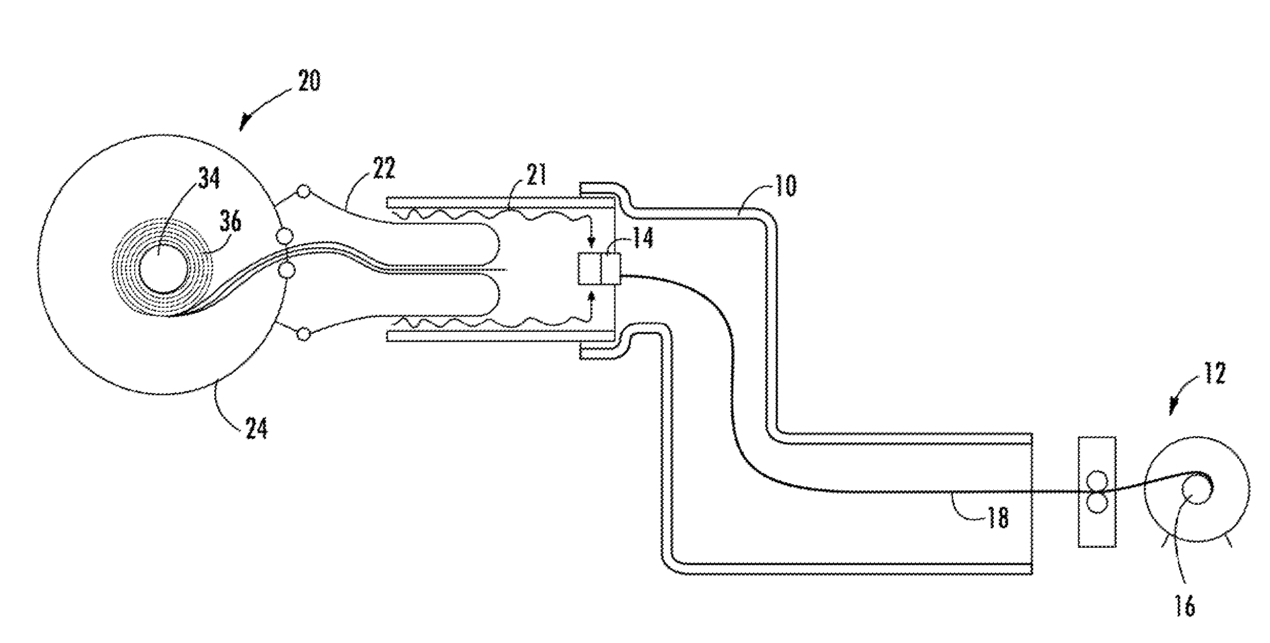
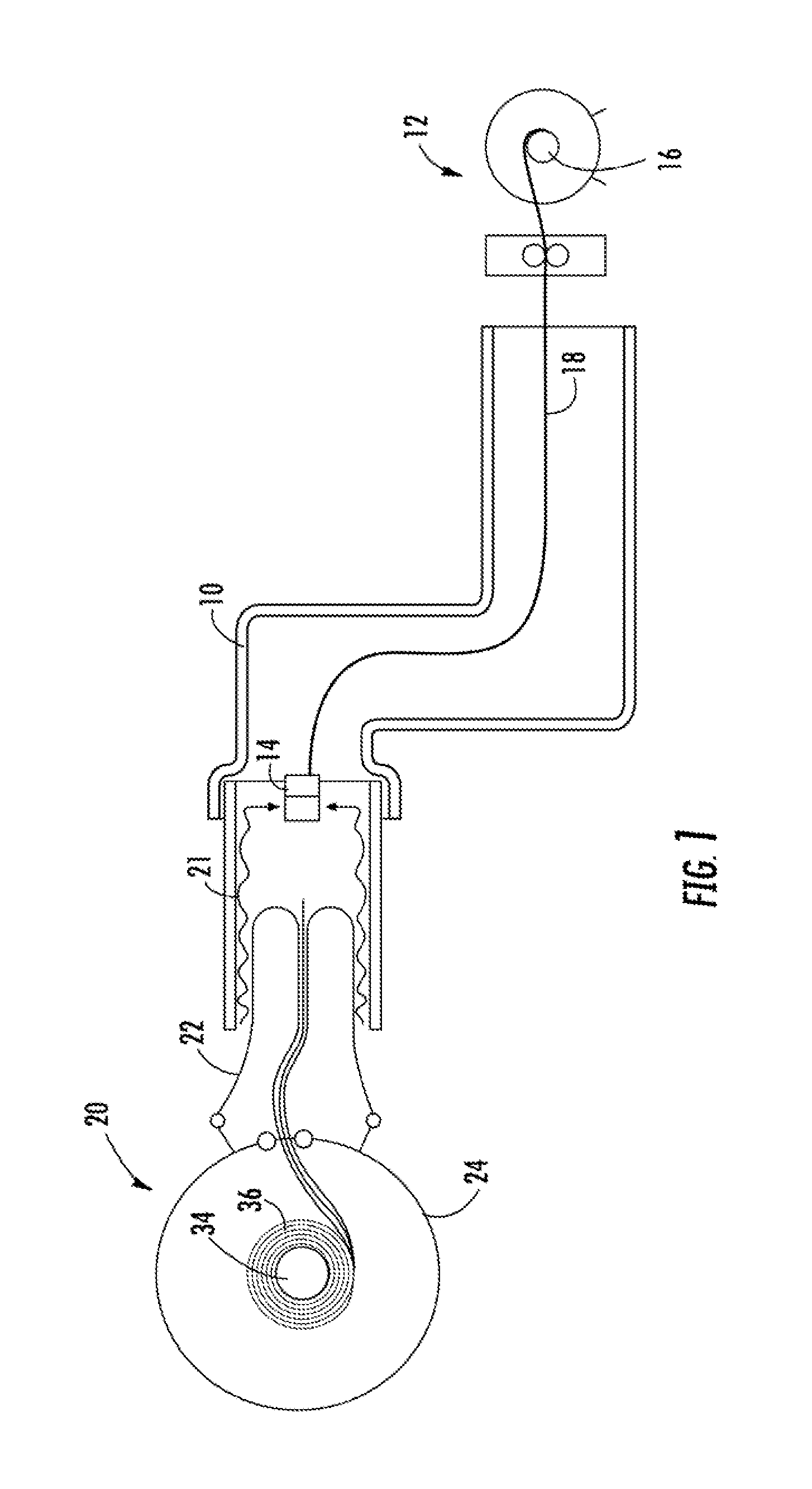
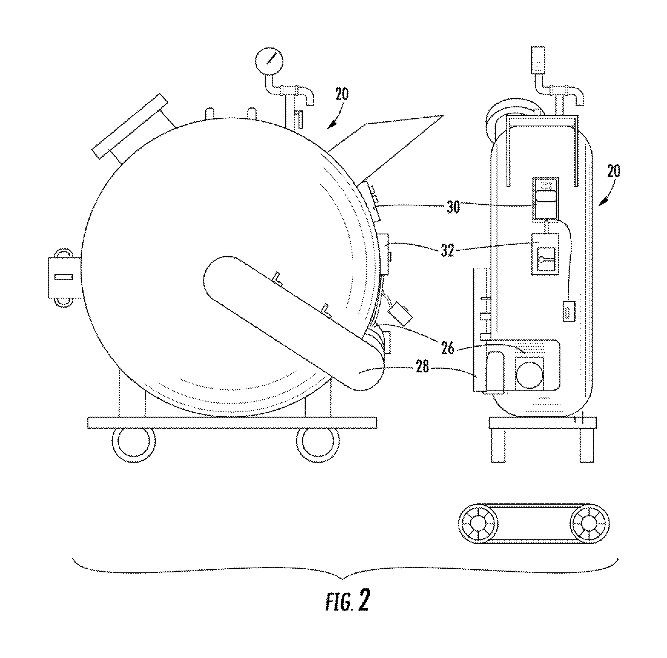
[0025]Now referring to the drawings, the inversion lining system of the present invention is schematically depicted and generally illustrated in FIGS. 1 and 2. In most general terms a spincast epoxy coating machine 12 is set up at one end of the host pipe 10. The spincaster 14 is pulled through the host pipe 10 via winch 16 and cable 18, or by a rock bore machine. At the other end of the host pipe 10, a computer controlled inversion machine 20 is set up. The interior surface of the host pipe 10 is coated with wet uncured spray applied epoxy 21 at a set speed as the spincaster 14 is retrieved. The inversion machine 20 loaded with dry liner 22 inside the inversion bag 24 is inverted into the host pipe 10 and into the wet epoxy 21. The payout speed of the inversion liner 22 is computer controlled at a constant speed and internal pressure. The dry inversion liner 22 is forced through the wet epoxy at a controlled speed such that the slow rate of inversion prevents air from being trapped...


PUM

PropertyMeasurementUnit
internal pressureaaaaaaaaaa
flexural modulusaaaaaaaaaa
inversion pressureaaaaaaaaaa

Abstract

A method and system for applying a liner to an underground utility structure is provided. First a layer of epoxy is applied to the interior surface of the host pipe using a machine such as a spincast machine. A dry liner is inverted into the pipe directly behind the coating application at a limited speed and pressure. A drag is set on the inversion equipment relative to the speed of the epoxy spinner unit to control inversion speed. Once the liner is completely inverted the internal pressure of the liner is raised and infused into the uncured epoxy.

Description

CROSS-REFERENCE TO RELATED APPLICATIONS[0001]This application is related to and claims priority from earlier filed U.S. Provisional Patent Application No. 61 / 832,433, filed June 7, 2013.BACKGROUND OF THE INVENTION[0002]The present invention relates generally to a method for repairing a distressed pipeline by installing a liner inside of the pipeline. More specifically, the present invention relates to a process wherein a curable resin system is applied to the inside walls of the pipeline in a two part process where first a resin is spun onto the pipeline wall. Next, a dry liner is inverted into the pipe and slowly pressurized to bed it into the uncured epoxy to wet out the liner until cured.[0003]Throughout developed parts of the world, there are numerous pipeline conduits that run underground in order to provide utility services to businesses and residences. These utilities include water lines, sewer pipes, storm water drains, and the like. Since these pipelines are installed under...

Claims


Application Information

Patent Timeline
Patent Type & Authority Applications(United States)
IPC IPC(8): F16L55/165F16L55/18
CPCF16L55/1651F16L55/18F16L55/1654B29C63/36B32B1/08B32B5/022B32B2255/26B32B2260/021B32B2260/046B32B2307/546B32B2581/00B32B2597/00
Inventor WARREN, DANNY
Owner WARREN ENVIRONMENTAL & COATING LLC
Why Eureka
Try Eureka