Flow thermal stress turbocharger turbine housing divider wall

a technology of thermal stress and turbocharger, which is applied in the direction of machines/engines, stators, liquid fuel engines, etc., can solve the problems of inaccuracy of cast parts, inability to accurately reproduce cast parts, and easy cracking of the area, so as to improve the durability of the divider wall and resist the propensity for cracking

Inactive Publication Date: 2015-01-22
BORGWARNER INC
View PDF3 Cites 13 Cited by
  • Summary
  • Abstract
  • Description
  • Claims
  • Application Information

AI Technical Summary

Benefits of technology

[0026]The inventors set about to improve the durability of the divider wall by designing the divider wall from a thermodynamic rather than purely aerodynamic vantage point. The inventors studied a variety of divider wall shapes based on different definitions of curves in the development of this invention and discovered that it is in fact possible to design a divider wall in a turbine housing of a turbocharger more able to resist the propensity for cracking.
[0027]The inventors discovered that, quantitatively, thermal energy is exponentially being passed to the exhaust gas, so the transient heat transfer from the divider wall is an exponential function, while the mass of the divider wall is a linear function. The inventors came to realize this mismatch, and set out to design a divider wall such that the mass of the divider wall and the transient heat transfer from the divider wall were more suitably matched.

Problems solved by technology

These requirements often result in compromises such as architectural requirements outside of the turbine housing, method of location, and mounting of the turbine housing to the bearing housing, and the transition from slice “A” to the turbine foot (7) results in turbine housing volutes of rectangular or triangular section, as well as in circular, or combinations of all shapes.
While this design facet provides efficient aerodynamics (the flow off the trailing edge does not become turbulent as the flow from one side of the divider wall attaches itself to the flow from the other side), the thin section around the intersection of the two sides of the trailing edge makes this area very susceptible to cracking.
A problem with this part of the turbine housing is that when molten iron is poured into a sand mold, the dross (which is a form of slag) from a reaction of the molten cast iron with Mg, O2, S, and Si is pushed into the trailing edge part of the divider wall.
The dross formations resemble cracks or flake graphite in the structure, which means that the part of the turbine housing closest to the turbine wheel has low impact and fatigue strength, which can result in foreign object damage (FOD) to the turbine wheel.
Since the typical cast iron turbine housing is cast into a sand mold, the process of building the mold out of a “cope” and “drag”, each of which are formed from opposite sides of a pattern, along with the insertion of cores where applicable, results is some lack of alignment with each other, known as core shift, which results in inaccuracy in the cast part.
Another source of inaccuracy is the fact that the mold is typically made from green foundry sand, which has a grain size of approximately 220 μm to 250 μm, so not only is there inherent inaccuracy between parts of the mold, but also in the surface finish.
Further, because the divider wall has lower thermal mass than do the other generally parallel walls, the divider wall both heats and cools more rapidly; which generates greater low cycle fatigue in the divider wall and hence the propensity for cracking.

Method used


Image

  • Flow thermal stress turbocharger turbine housing divider wall
  • Flow thermal stress turbocharger turbine housing divider wall
  • Flow thermal stress turbocharger turbine housing divider wall

Examples


Embodiment Construction

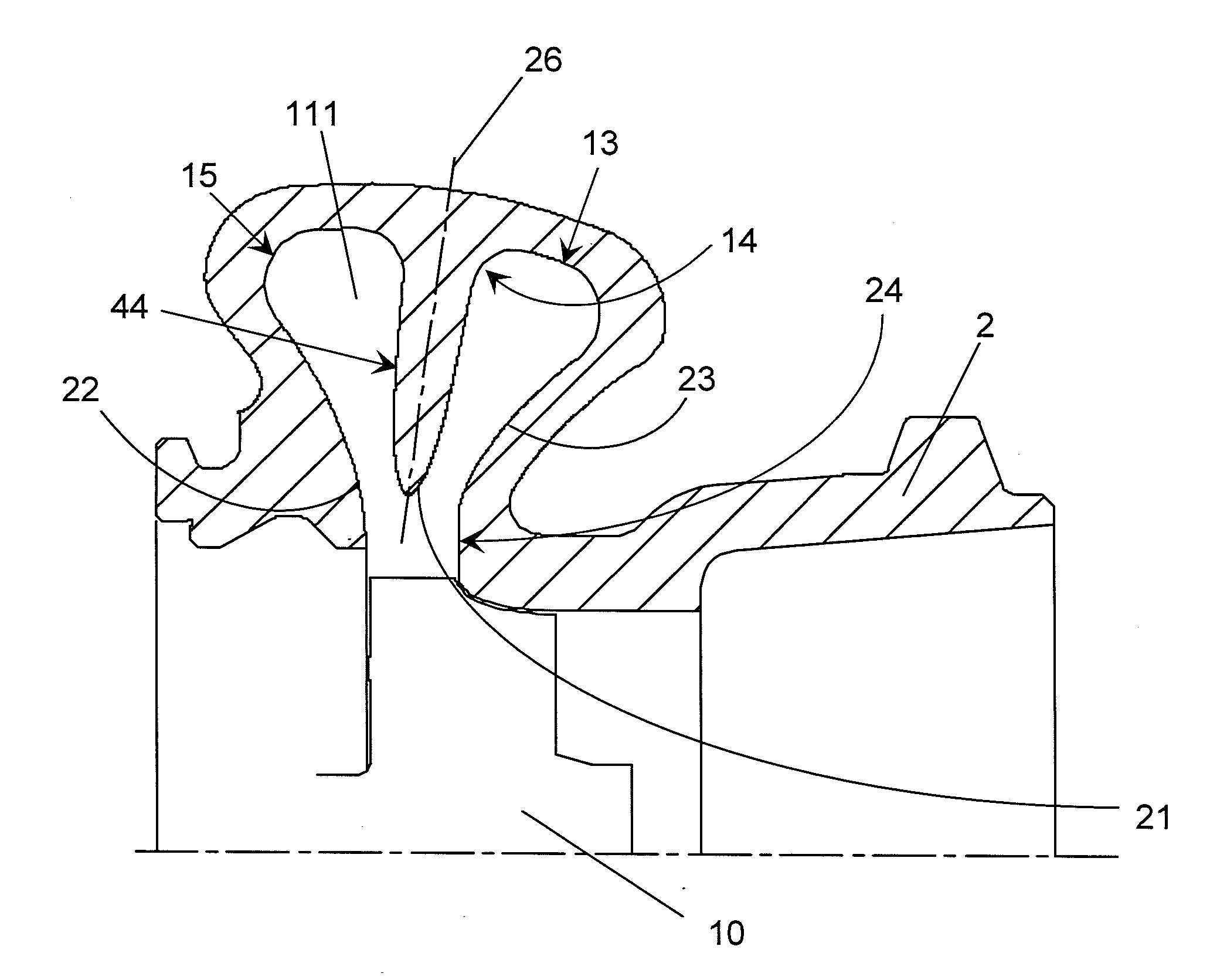
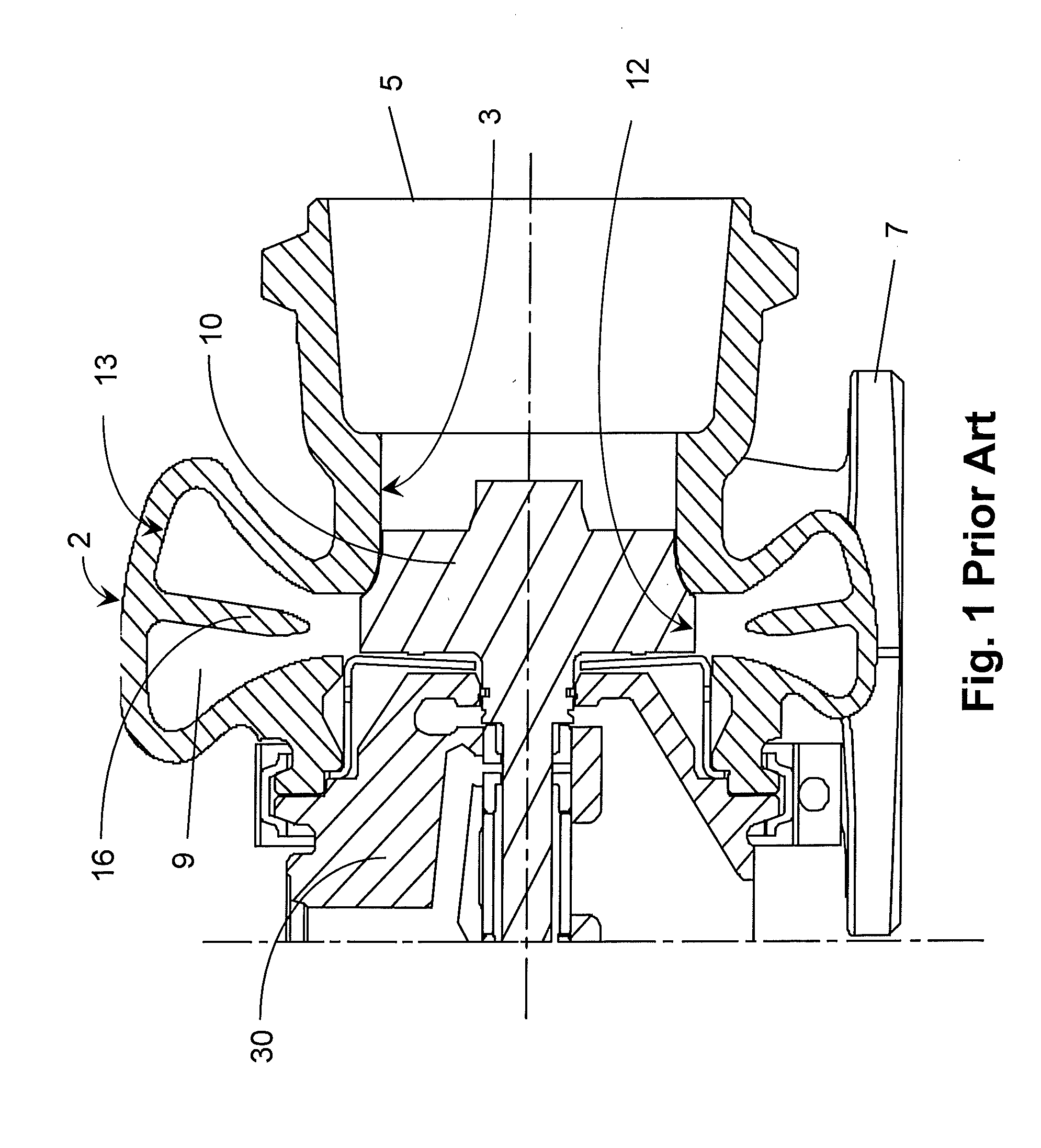
[0037]Divided turbine housings in turbochargers are used to sustain, in the turbine, the pulse energy originating from low engine speed combustion in the cylinder head. The exhaust pulses are propagated along the exhaust manifold, and upon reaching the turbine the divided turbine housing further maintains the pulses to deliver pulsed flow, as against steady state flow, to the turbine wheel. This pulse energy is then converted to rotational energy by the turbine wheel.

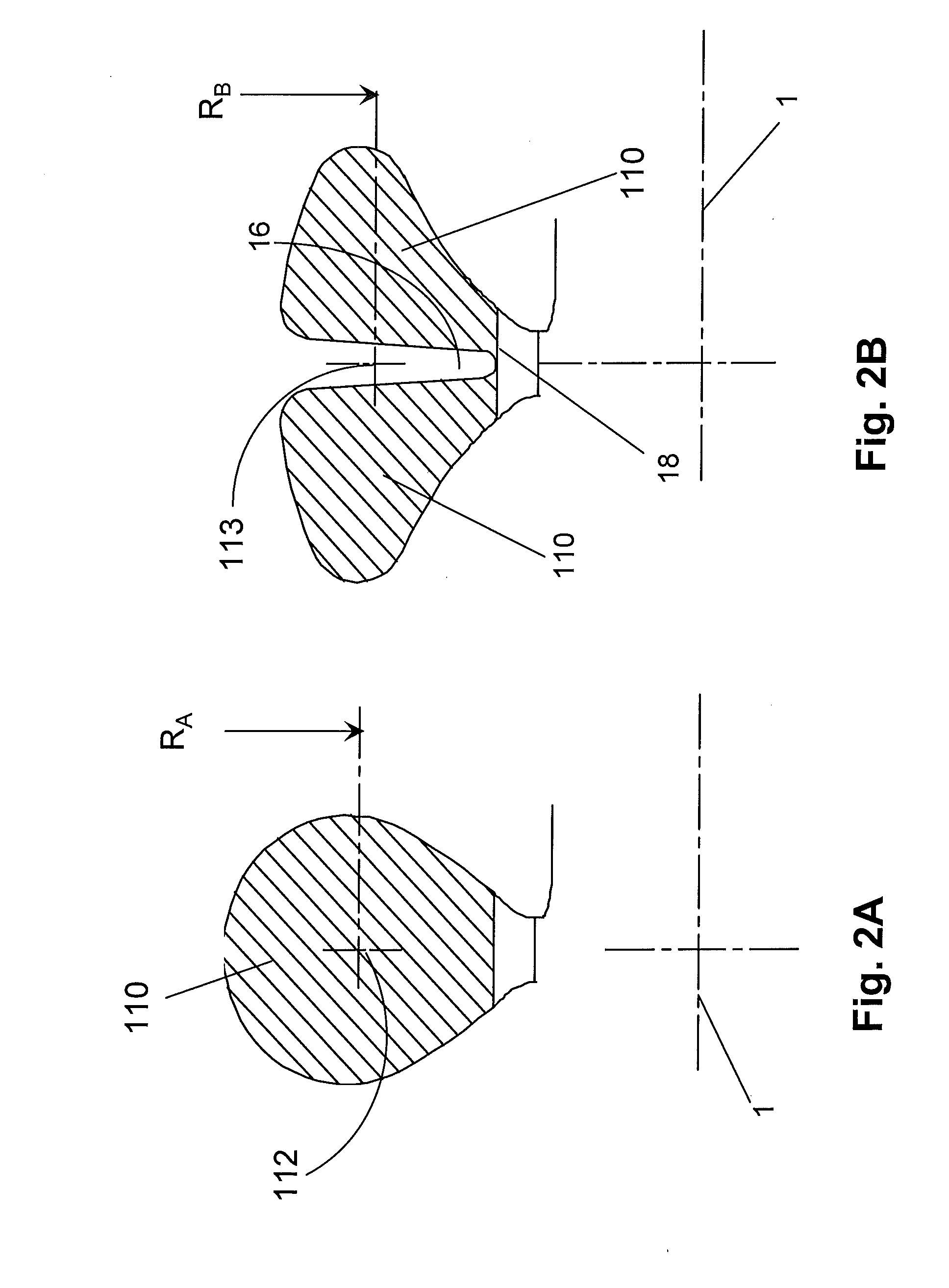
[0038]In an aerodynamic sense, the shape of the divider wall near the trailing edge (21) and the shape of the surface of the outer walls (22, 23) of the volute form a nozzle to guide the exhaust flow into the turbine wheel (10). As a result of this aerodynamic need, the design of the divider wall, the function of which is to segregate the pulses in the separate volutes (111) and to support the trailing edge (21) surfaces, has historically been left in the hands of the aerodynamics designers. The inventors and set about ...


PUM


Abstract

The propensity for turbocharger turbine divider wall to crack in the turbine housing is minimized by matching the mass of the divider wall more closely to the transient heat transfer between said divider wall and the exhaust gas flowing past it. This is achieved by providing said divider wall having a cross-sectional shape defined substantially by a Log2 curve.

Description

FIELD OF THE INVENTION[0001]This invention addresses the need for an improved turbocharger divided turbine housing design to reduce the propensity for crack initiation and propagation in the divider wall.BACKGROUND OF THE INVENTION[0002]Turbochargers are a type of forced induction system. They deliver air, at greater massflow than would be possible in the normally aspirated configuration, to the engine intake, allowing more fuel to be combusted, thus boosting the engine's horsepower without significantly increasing engine weight. This can enable the use of a smaller turbocharged engine, replacing a normally aspirated engine of a larger physical size, thus reducing the mass and aerodynamic frontal area of the vehicle.[0003]Turbochargers use the exhaust flow from the engine exhaust manifold to drive a turbine wheel (10), which is located in a turbine housing (2). Once the exhaust gas has passed through the turbine wheel, and the turbine wheel has extracted energy from the exhaust gas,...

Claims


Application Information

Patent Timeline
Patent Type & Authority Applications(United States)
IPC IPC(8): F01D25/24
CPCF01D25/24F05D2260/16F05D2220/40F05D2260/941F01D9/026F05D2240/14
Inventor SHOGHI, KIUMARSGARCIA ALCARAZ, ALEXANDREOBERSTE-BRANDENBURG, CLAUS
Owner BORGWARNER INC
Why Eureka
Try Eureka