Multi-reflection mass spectrometer

Active Publication Date: 2015-01-29
THERMO FISHER SCI BREMEN
View PDF1 Cites 54 Cited by
  • Summary
  • Abstract
  • Description
  • Claims
  • Application Information

AI Technical Summary

Benefits of technology

[0072]The ions are ejected from the storage multipole in a substantially parallel beam and accordingly, a first set of ions ejected from one end of the storage multipole emerge closer to the spectrometer or trap than a second set of ions ejected simultaneously from the other end of the storage multipole, due to the storage multipole inclination angle +θ/2, and accordingly the first set of ions would reach the time-of-flight mass spectrometer or trap before the second set of ions if no deflection means are implemented in between the storage multipole and the spectrometer or trap. The electrostatic deflector compensates the said time-of-flight difference and, simultaneously, doubles the ion beam inclination. To illustrate the time-of-flight compensation, we firstly suppose the ion beam to comprise positive ions, and the first set of ions pass through a first region of the deflector and the second set of ions pass through the second region of the deflector without substantially overlapping inside the

Problems solved by technology

However this system lacked any means to prevent beam divergence in the drift direction.
Due to the initial angular spread of the injected ions, after multiple reflections the beam width may exceed the width of the detector making any further increase of the ion flight time impractical due to the loss of sensitivity.
Ion beam divergence is especially disadvantageous if trajectories of ions that have undergone a different number of reflections overlap, thus making it impossible to detect only ions having undergone a given number of oscillations.
As a result, the design has a limited angular acceptance and/or limited maximum number of reflections.
Furthermore, the ion mirrors did not provide time-of-flight focusing with respect to the initial ion beam spread across the plane of the folded path, resulting in degraded time-of-flight resolution for a wide initial beam angular divergence.
However these arrangements were complex to manufacture, being composed of multiple high-tolerance mirrors that required precise alignment with one another.
The system had no means for controlling beam divergence in the drift direction, and this, together with the use of gridded mirrors which reduced the ion flux at each reflection, limited the useful number of reflections and hence flight path len

Method used


Image

  • Multi-reflection mass spectrometer
  • Multi-reflection mass spectrometer
  • Multi-reflection mass spectrometer

Examples


Embodiment Construction

[0092]Various embodiments of the present invention will now be described by way of the following examples and the accompanying figures.

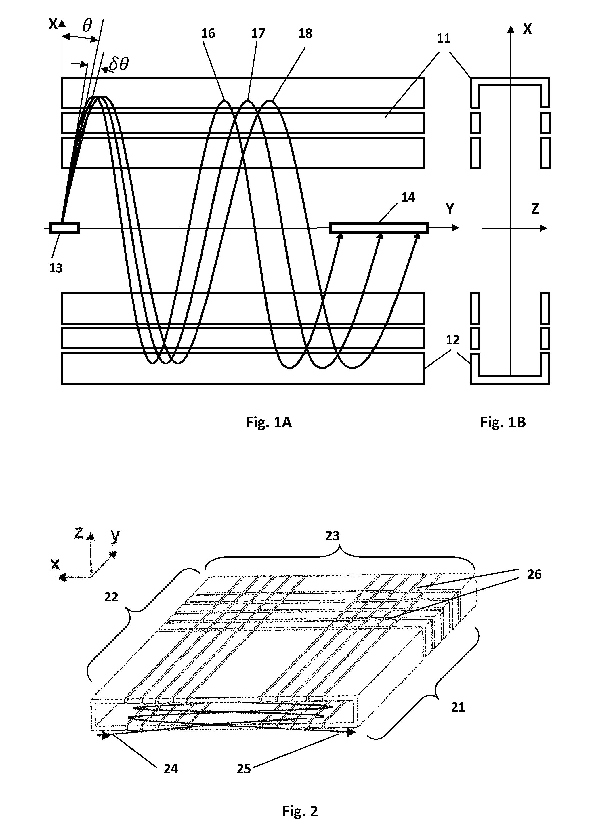
[0093]FIG. 1A and FIG. 1B are schematic diagrams of a multi-reflection mass spectrometer comprising parallel ion-optical mirrors elongated linearly along a drift length, illustrative of prior art analysers. FIG. 1A shows the analyser in the X-Y plane and FIG. 1B shows the same analyser in the X-Z plane. Opposing ion-optical mirrors 11, 12 are elongated along a drift direction Y and are arranged parallel to one another. Ions are injected from ion injector 13 with angle θ to axis X and angular divergence δθ, in the X-Y plane. Accordingly, three ion flight paths are depicted, 16, 17, 18. The ions travel into mirror 11 and are turned around to proceed out of mirror 11 and towards mirror 12, whereupon they are reflected in mirror 12 and proceed back to mirror 11 following a zigzag ion flight path, drifting relatively slowly in the drift direction Y. After...


PUM


Abstract

A multi-reflection mass spectrometer is provided comprising two ion-optical mirrors, each mirror elongated generally along a drift direction (Y), each mirror opposing the other in an X direction, the X direction being orthogonal to Y, characterized in that the mirrors are not a constant distance from each other in the X direction along at least a portion of their lengths in the drift direction. In use, ions are reflected from one opposing mirror to the other a plurality of times while drifting along the drift direction so as to follow a generally zigzag path within the mass spectrometer. The motion of ions along the drift direction is opposed by an electric field resulting from the non-constant distance of the mirrors from each other along at least a portion of their lengths in the drift direction that causes the ions to reverse their direction.

Description

FIELD OF THE INVENTION[0001]This invention relates to the field of mass spectrometry, in particular high mass resolution time-of-flight mass spectrometry and electrostatic trap mass spectrometry utilizing multi-reflection techniques for extending the ion flight path.BACKGROUND OF THE INVENTION[0002]Various arrangements utilizing multi-reflection to extend the flight path of ions within mass spectrometers are known. Flight path extension is desirable to increase time-of-flight separation of ions within time-of-flight (TOF) mass spectrometers or to increase the trapping time of ions within electrostatic trap (EST) mass spectrometers. In both cases the ability to distinguish small mass differences between ions is thereby improved.[0003]An arrangement of two parallel opposing mirrors was described by Nazarenko et. al. in patent SU1725289. These mirrors were elongated in a drift direction and ions followed a zigzag flight path, reflecting between the mirrors and at the same time drifting...

Claims


Application Information

Patent Timeline
IPC IPC(8): H01J49/40H01J49/06H01J49/00
CPCH01J49/406H01J49/061H01J49/004H01J49/0027
Inventor GRINFELD, DMITRYMAKAROV, ALEXANDER
Owner THERMO FISHER SCI BREMEN
Why Eureka
Try Eureka