Dust separation from the crude gas of an entrained flow gasifier

Active Publication Date: 2015-02-05
SIEMENS ENERGY GLOBAL GMBH & CO KG
View PDF5 Cites 0 Cited by
  • Summary
  • Abstract
  • Description
  • Claims
  • Application Information

AI Technical Summary

Benefits of technology

The patent describes a gasification plant designed to handle higher levels of dust and particles. The plant uses a combination of coarse and fine particle separators in a purification process to remove the most damaging particles. The process includes a quenching chamber, a washing column, and a fine droplet separator. The purified gas then flows through a heat exchanger to cool it and remove ultrafine particles. The plant aims to remove over 99.9% of particles in this process. The technical effect of this system is to improve the quality and efficiency of gas production by reducing the amount of harmful particles in the gas stream.

Problems solved by technology

This results in increased wear in the classifying separators and lines which conduct crude gas, which can cause safety-relevant leaks and service life restrictions.
For dust quantities greater than 2 g / m3 under normal conditions, this arrangement consisting of two Venturi washers and a partial condensation step is only partially adequate or is inadequate and can result in substantially higher dust concentrations in the intake of the CO conversion and also increased erosion in the Venturi washers and furthermore in soiling and blocking in the partial condenser and the downstream systems.

Method used


Image

  • Dust separation from the crude gas of an entrained flow gasifier
  • Dust separation from the crude gas of an entrained flow gasifier
  • Dust separation from the crude gas of an entrained flow gasifier

Examples


Embodiment Construction

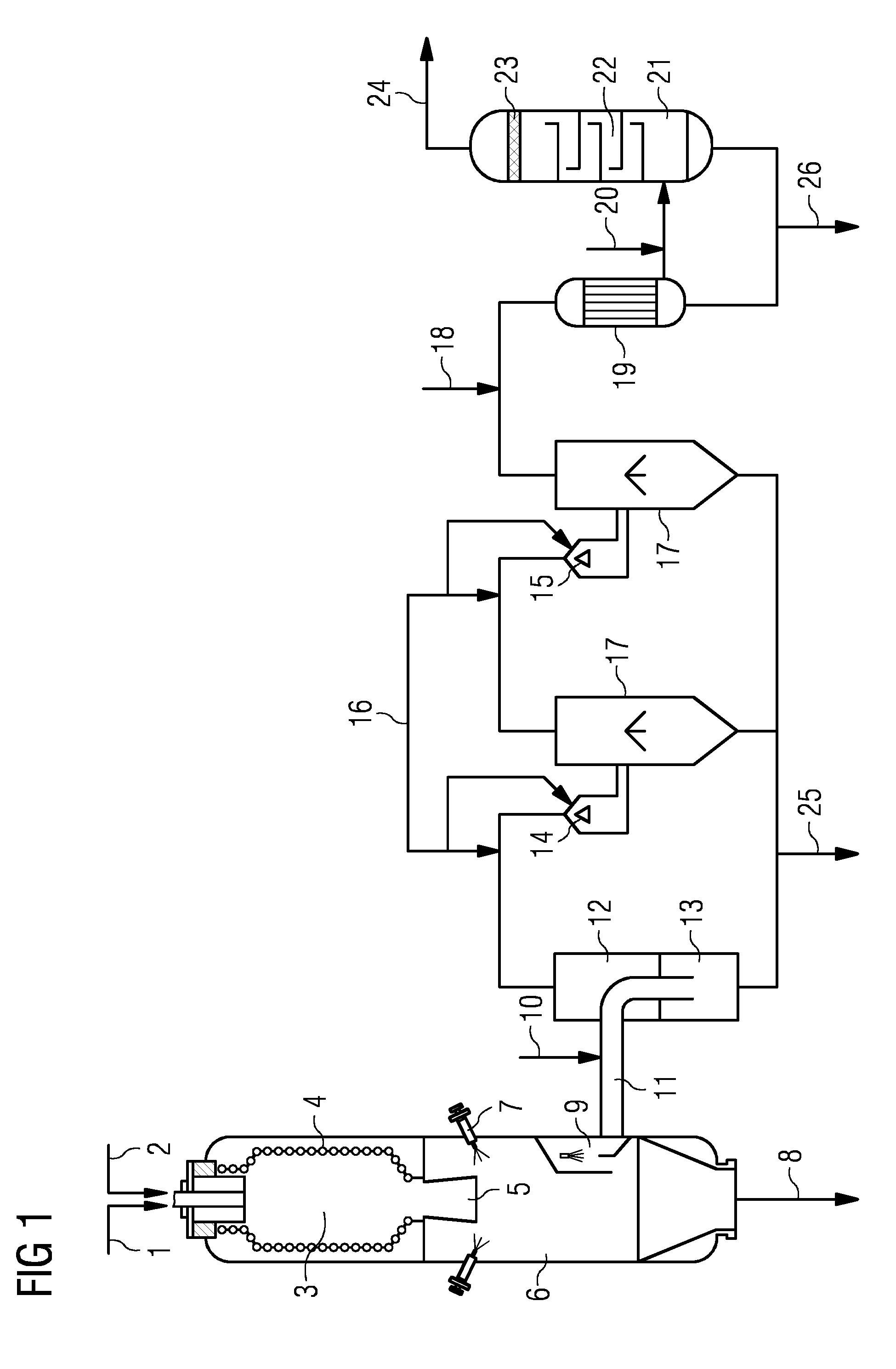
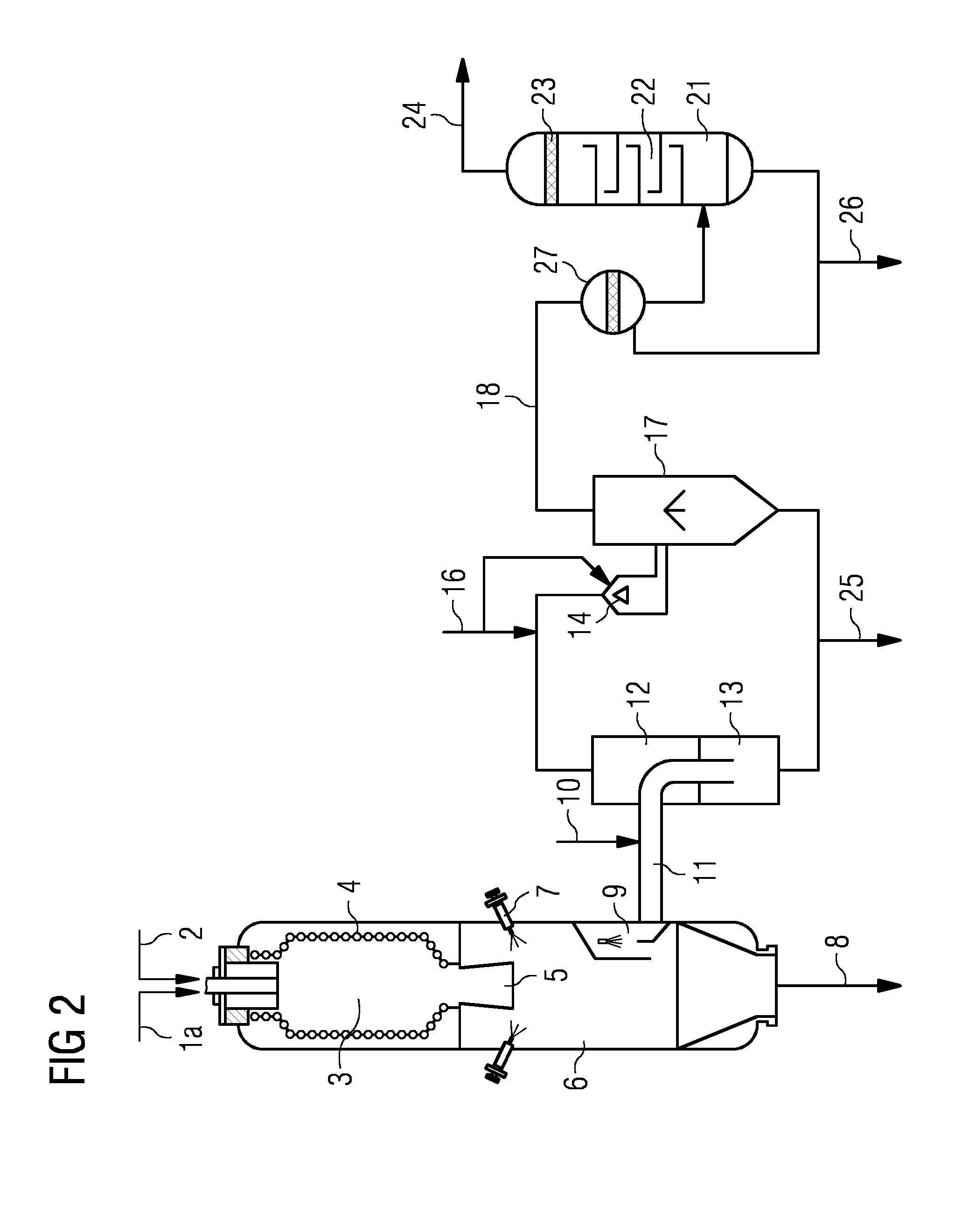
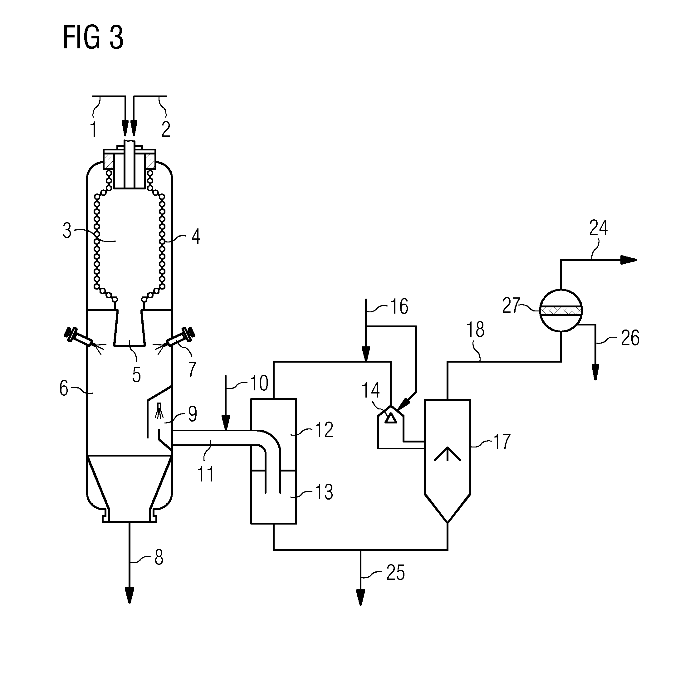
[0012]In the figures, identical reference signs identify identical elements.

[0013]80 Mg / h pulverized dust made of a lean coal are supplied to an entrained flow reactor having a gross output of 500 MW, as shown in FIG. 1, according to the principle of pneumatic conveying using carbon dioxide as a carrier gas via the dust conveyor line 1 and converted jointly with 45,000 m3 / h oxygen under normal conditions via line 2 in the gasification chamber 3 at temperatures of 1650° C. and a pressure of 4.5 MPa into a crude synthesis gas. The gasification chamber 3 is delimited by a cooling screen 4. The fuel ash is melted at the mentioned gasification temperatures and largely applied to the cooling screen, runs downward, and reaches the downstream quenching chamber 6 via the crude gas and slag discharge opening 5. The crude gas quantity is 135,000 m3 / h under normal conditions. The temperatures after the quenching are between 150 and 250° C., the crude gas is saturated with water vapor. Not all o...


PUM


Abstract

A multistage gas washing system is applied for dust separation from crude gases of entrained flow gasification of pulverized fuels under pressures up to 10 MPa and temperatures which are greater than the melting point of the fuel ash. A first stage comprises a modified quenching system and a downstream washing column, which operates as a bubble column. A second washing stage comprises one or more Venturi washers connected in series. A third washing stage comprises multiple high-pressure atomization units of washing water, a partial condenser for cooling the crude gas by 1 to 15° C. with condensate formation, and a separation column, which is equipped with washing surfaces and a plastic-coated demister.

Description

CROSS-REFERENCE TO RELATED APPLICATIONS[0001]The present application claims the priority of German Patent Application No. 102013215120.9, filed Aug. 1, 2013, the contents of which are incorporated by reference herein.TECHNICAL FIELD[0002]The invention relates to a multistage crude gas washing system having a high degree of separation of particles, in particular fine dust, during the production of crude gas rich in CO and H2 in an entrained flow gasification plant by reaction of ash, but also slag-forming fuels, under pressures up to 10 MPa and temperatures up to 1900° C.TECHNICAL BACKGROUND[0003]Pulverized fuels are understood to include finely-ground coals of different degrees of carbonization, dusts made of biomasses, products of the thermal pretreatment such as coke, dried products by way of “torrefaction”, and fractions having high calorific value from municipal and industrial residual materials and waste materials. The pulverized fuels can be supplied as a gas-solid suspension ...

Claims


Application Information

Patent Timeline
IPC IPC(8): C10J3/84
CPCC10J3/84C10J3/485C10J2300/093C10K1/101
Inventor HANNEMANN, FRANKSCHINGNITZ, MANFRED
Owner SIEMENS ENERGY GLOBAL GMBH & CO KG
Why Eureka
Try Eureka