Honeycomb filter
- Summary
- Abstract
- Description
- Claims
- Application Information
AI Technical Summary
Benefits of technology
Problems solved by technology
Method used
Image
Examples
first embodiment
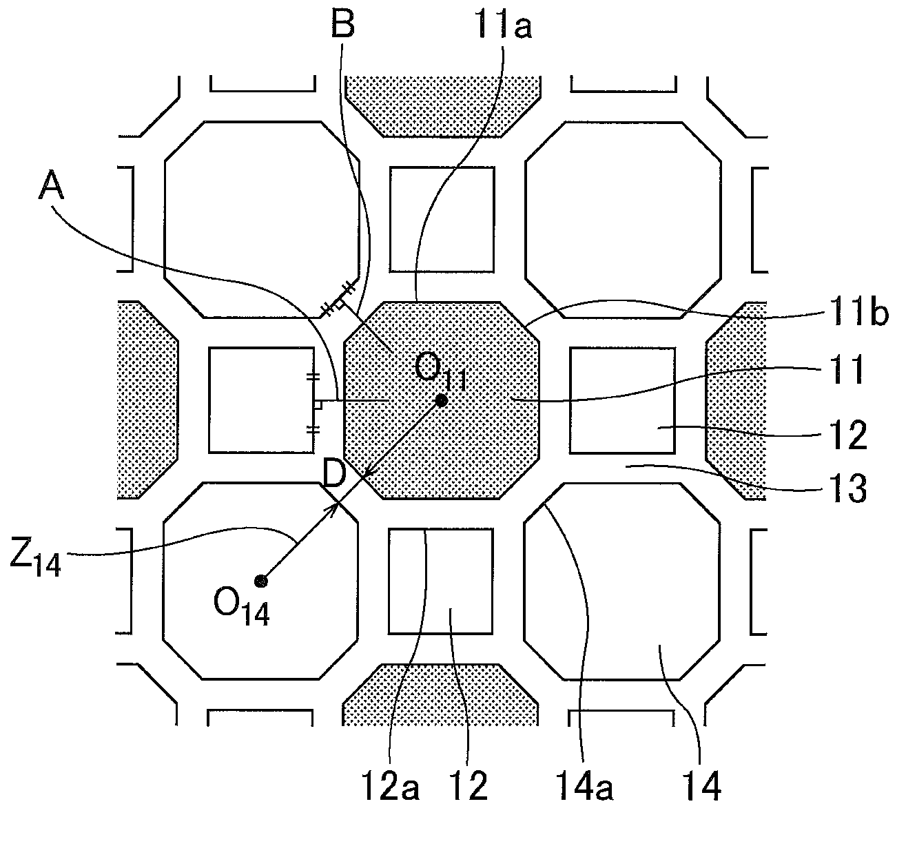
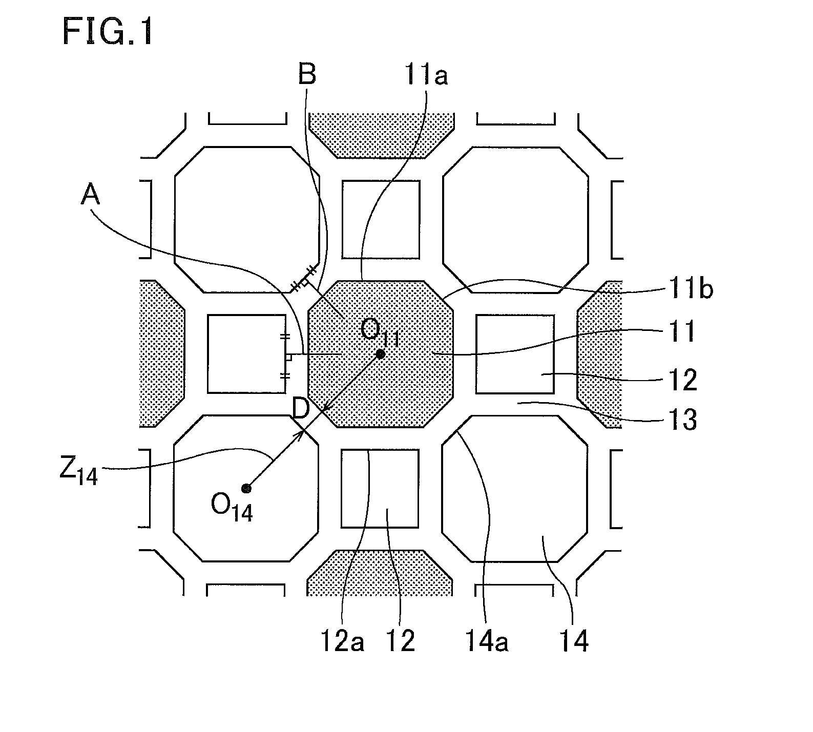
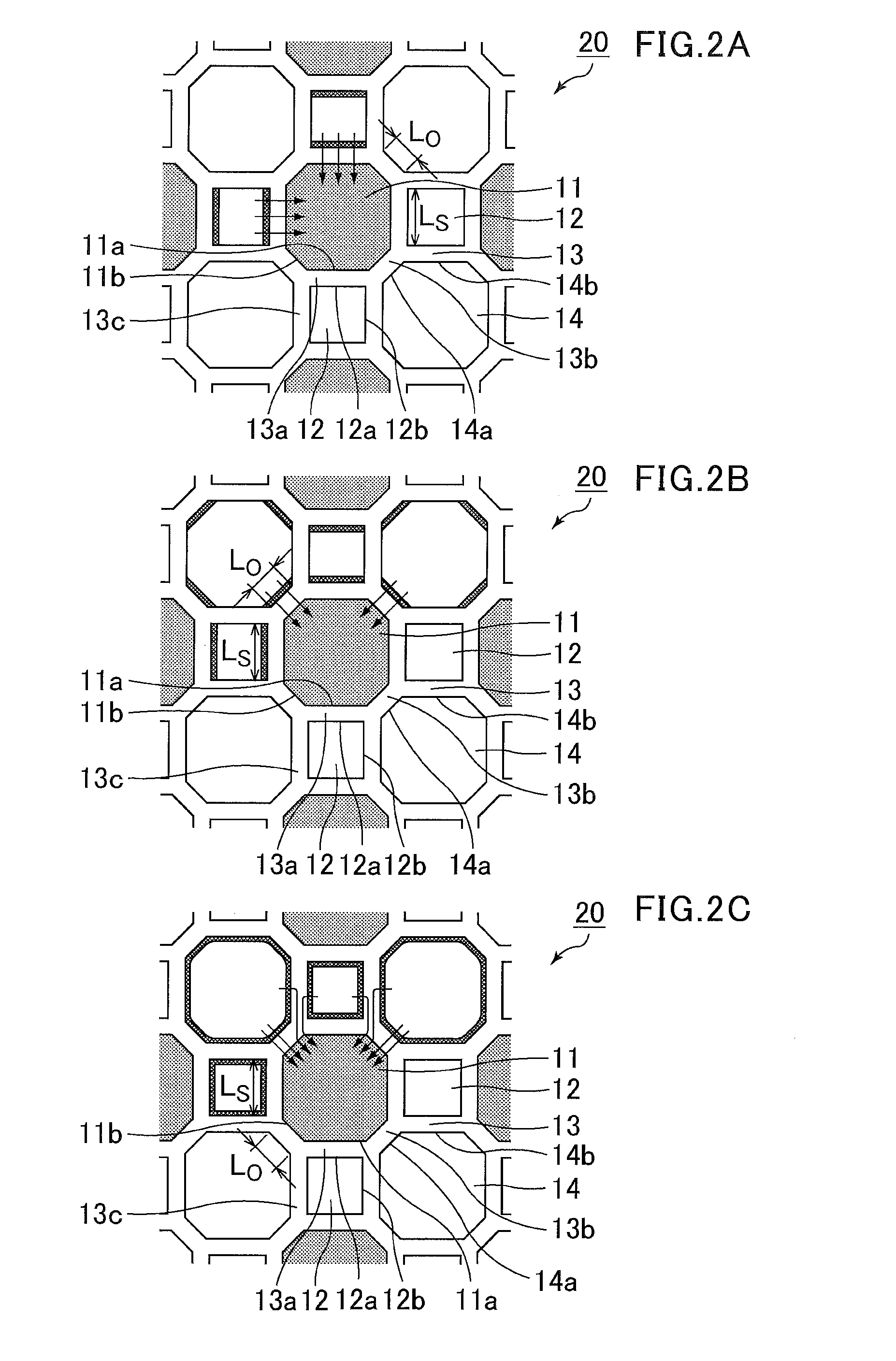
[0252]The following will discuss a honeycomb filter of the first embodiment of the present invention.
[0253]The honeycomb filter according to the first embodiment of the present invention includes a plurality of honeycomb fired bodies. Each honeycomb fired body includes porous cell walls that define rims of a plurality of cells that serve as the channels of exhaust gas; exhaust gas emission cells each having an open end at an exhaust gas emission side and a plugged end at an exhaust gas introduction side; and exhaust gets introduction cells each having an open end at the exhaust gas introduction side and a plugged end at the exhaust gas emission side, the exhaust gas introduction cells including first exhaust gas introduction cells and second exhaust gas introduction cells. Each honeycomb fired body has an outer wall on the periphery thereof, and a plurality of honeycomb fired bodies are combined with one another by adhesive layers residing therebetween.
[0254]In regard to the cells o...
example 1
[0367]A mixture was obtained by mixing 40.6% by weight of a silicon carbide coarse powder having an average particle size of 22 μm, 17.4% by weight of a silicon carbide fine powder having an average particle size of 0.5 μm, and 10.6% by weight of acrylic resin baaing an average particle size of 40 μm as a pore-forming agent. To the mixture were added 6.4% by weight of an organic binder (methylcellulose), 3.0% by weight of a lubricant (UNILUB, manufactured by NOF Corporation), 1.4% by weight of glycerin, 20.6% by weight of water and then kneaded to prepare a wet mixture. Thereafter, the wet mixture was extrusion-molded (molding process).
[0368]This process provides a raw honeycomb molded body which had the same shape as that of the honeycomb fired body 10 shown in FIG. 4A and in which the cells were not plugged. Herein, the size of each sell was set such that the cross sectional area of each first exhaust gas introduction cell 12 was 0.7 mm2 or smaller.
[0369]Next, the raw honeycomb mo...
second embodiment
[0411]The following will describe a honeycomb filter according to the second embodiment of the present invention.
[0412]The honeycomb filter according to the second embodiment includes exhaust gas emission cells each having an open end at an exhaust gas emission side and a plugged end at an exhaust gas introduction side, and exhaust gas introduction cells each having an open end at the exhaust gas introduction side and a plugged end at the exhaust gas emission side, the exhaust gas introduction cells including first exhaust gas introduction cells and second exhaust gas introduction cells, and the cross sectional area of each first exhaust gas introduction cell in a direction perpendicular to the longitudinal direction of the cell is 0.7 mm2 or smaller.
[0413]In addition, the exhaust gas emission cells are each adjacently surrounded fully by the first exhaust gas introduction cells and the second exhaust gas introduction cells across the porous cell walls.
[0414]In the cross section per...
PUM
| Property | Measurement | Unit |
|---|---|---|
| cross sectional area | aaaaa | aaaaa |
| area | aaaaa | aaaaa |
| thickness | aaaaa | aaaaa |
Abstract
Description
Claims
Application Information
 - R&D
- Intellectual Property
- Life Sciences
- Materials
- Tech Scout
- Unparalleled Data Quality
- Higher Quality Content
- 60% Fewer Hallucinations
Browse by: Latest US Patents, China's latest patents, Technical Efficacy Thesaurus, Application Domain, Technology Topic, Popular Technical Reports.
© 2025 PatSnap. All rights reserved.Legal|Privacy policy|Modern Slavery Act Transparency Statement|Sitemap|About US| Contact US: help@patsnap.com


