Eureka AIR delivers breakthrough ideas for toughest innovation challenges, trusted by R&D personnel around the world.

Method for operating flash vessel

Inactive Publication Date: 2015-02-12
SUMITOMO METAL MINING CO LTD
View PDF2 Cites 6 Cited by
  • Summary
  • Abstract
  • Description
  • Claims
  • Application Information

AI Technical Summary

Benefits of technology

The patent describes a process for leaching ores using high-pressure acid. The process involves preparing an ore slurry with a specific concentration and size of particles, heating and pressurizing the slurry with a preheater, and then feeding it into an autoclave to leach impurity elements. The leached slurry is then transferred to a flash vessel to reduce temperature and pressure, and neutralize free sulfuric acid. The process also involves a preneutralization process and solid-liquid separation to separate the leaching residue and the leachate. The technical effect of the process is to efficiently remove impurities from ores and obtain a high-quality leachate.

Problems solved by technology

For example, a leaching method using chlorine gas as a leaching agent is performed by using an oxidation-reduction potential in a leachate, and therefore a pressure in an autoclave is not directly controlled, and not stable or fixed during leaching operation, and it varies depending on injection amount of chlorine gas which is controlled by the oxidation-reduction potential.
However, problems about the occurrences of damage and the like to the steam discharge pipe, the slurry discharge pipe and the slurry discharge valve have not been completely solved out, and approximately ten occurrences of damage to the steam discharge pipe and the slurry discharge valve have taken place per year operation, and therefore a practical technique to further reduce the problems about the occurrence of damage has been required.
A cause about the above mentioned damages is presumed to lie in insufficient control of liquid level.
In other words, at the time when a leached slurry having a high temperature and a high pressure is fed into a flash vessel and steam is generated accordingly, a liquid surface of the slurry is presumed not to be flat, or rather, it is presumed that steam generated from a deep part of the slurry causes a liquid level thereof to violently vary, whereby the control of the liquid level is insufficient.
In other words, there is only the above-mentioned presumption because, in the high-pressure acid leaching process adopted as hydrometallurgy of nickel oxide ores and using an autoclave, a flash vessel configured to reduce the temperature and pressure of a slurry obtained after leaching a raw material slurry under high temperature and high pressure by using an autoclave has a large size and furthermore is to be applied to a strongly acidic slurry, and therefore it is technically hard to provide an observation window to the flash vessel, and therefore it is substantially impossible to visually observe the inside of the flash vessel.
However, the method is hard to directly apply to solve the above-mentioned problems because conditions are too different, that is, a target to be treated is a slurry of organic sludge, the steam pressure is 2.5 atmospheres at most, and the like.
Furthermore, for example, Patent Literature 3 discloses a technique for controlling the refrigerant charge into a refrigerant vapor compression system by use of at least one sensor which detects the level of a liquid refrigerant in a flash vessel used for the system, but the technique is used for a float type sensor, a supersonic sensor, or the like as a sensor, and accordingly is applicable only when a liquid surface is flat, and hence the technique is hard to apply to solve the above-mentioned problems.

Method used


Image

  • Method for operating flash vessel
  • Method for operating flash vessel
  • Method for operating flash vessel

Examples


example 1

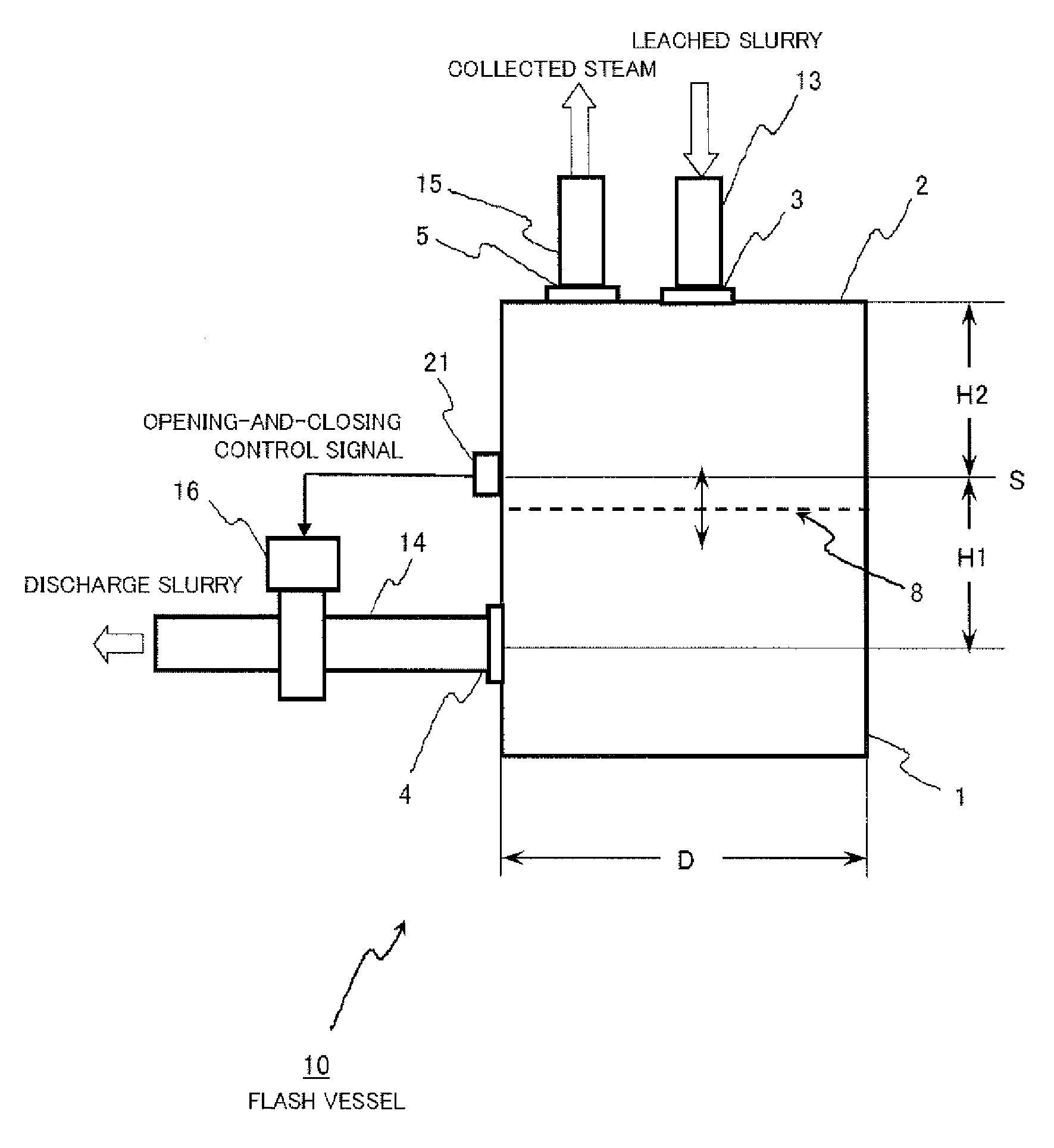
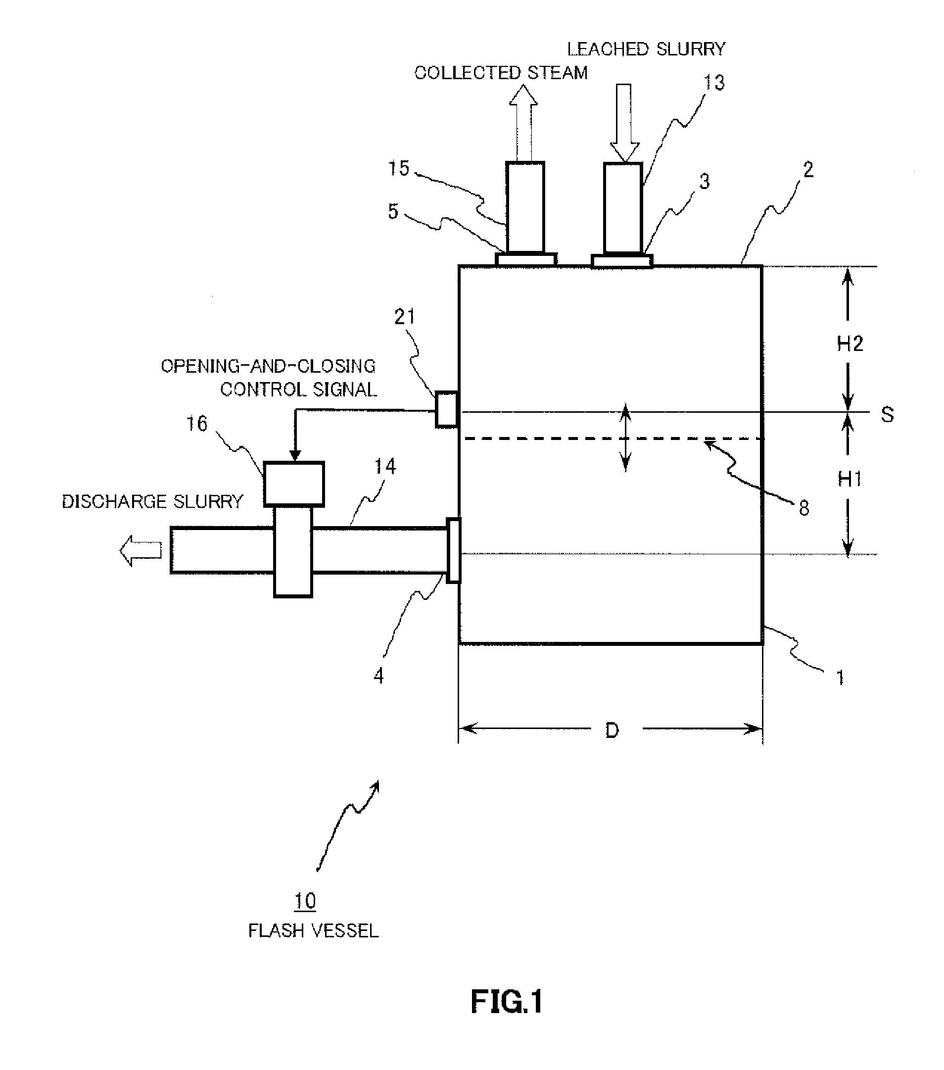
[0074]There was used a practical plant for nickel oxide ores, the plant including the above-mentioned practical equipment example for the high-pressure acid leaching process.

[0075]An operation was carried out for six months, the operation being such that, using an ore slurry shown in Table 1, a leached slurry was prepared to have a temperature of approximately 245 degrees C. and a pressure of approximately 4 MPaG at an outlet of an autoclave, and the leached slurry was fed into a first-stage flash vessel, and subsequently transferred to second-stage and third-stage flash vessels in order, whereby the temperature and pressure of the leached slimy was reduced to normal temperature and pressure.

[0076]As a result, troubles due to damage to a steam discharge pipe, a slurry discharge pipe, or a slurry discharge valve did not occur.


PUM

PropertyMeasurementUnit
Electric dipole momentaaaaaaaaaa
Temperatureaaaaaaaaaa
Pressureaaaaaaaaaa

Abstract

The present invention is such that, with H1 being the height from a slurry outlet to a control liquid level, H2 being the height from the control liquid level to the top of a flash vessel, and being the diameter of the flash vessel, 0.35D≦H1≦0.45D, and 0.75D≦H2≦0.85D, and at least one liquid level sensor detects a slurry liquid surface at a control liquid level; when the liquid level sensor detects a slurry liquid surface which has risen, a slurry discharge valve installed on a slurry discharge pipe derived from the flash vessel is opened; and when the liquid level sensor detects a slurry liquid surface which has fallen, the slurry discharge valve is closed, whereby opening and closing of the valve is appropriately controlled thereby to reduce troubles with a steam discharge pipe, the slurry discharge pipe, and the slurry discharge valve.

Description

FIELD OF THE INVENTION[0001]The present invention relates to a method for operating a flash vessel, specifically relates to a method for operating a flash vessel (a vessel for reducing temperature and pressure) in a high-pressure acid leaching process, the high-pressure acid leaching process being such that a raw material slurry is leached by using an autoclave (high-pressure reaction vessel) under high temperature and high pressure, and then the temperature and pressure of a leached slurry is reduced to normal temperature and pressure by using the flash vessel. The present application asserts priority rights based on JP Patent Application 2012-005441 filed in Japan on Jan. 13, 2012. The total contents of disclosure of the Patent Application of the senior filing date are to be incorporated by reference into the present Application.BACKGROUND OF THE INVENTION[0002]In recent years, with the development of a material having corrosion resistance under high temperature and high pressure ...

Claims


Application Information

Patent Timeline
IPC IPC(8): C22B3/00
CPCC22B23/0415C22B3/02C22B3/04B01J3/04B01J4/008B01J2219/00182Y02P10/20
Inventor MATSUBARA, SATOSHINAKAI, OSAMUKYODA, YOJISAKAMOTO, TAKASHI
Owner SUMITOMO METAL MINING CO LTD
Why Eureka
Eureka Blog
Learn More