Eureka AIR delivers breakthrough ideas for toughest innovation challenges, trusted by R&D personnel around the world.

Compact multi-stage turbo pump

Inactive Publication Date: 2015-02-19
JAGUAR LAND ROVER LTD
View PDF6 Cites 6 Cited by
  • Summary
  • Abstract
  • Description
  • Claims
  • Application Information

AI Technical Summary

Benefits of technology

This patent describes a design for a wheel with a hole in it that has vanes on it. These vanes can be straight or shaped to affect the flow of gas. In a compressor, they can create a pre-whirl that helps with the next step in the process. On the turbine side, they can help gather energy from the exhaust gas or make the whole system more efficient.

Problems solved by technology

Ideally the exhaust driven turbine would work effectively at all engine speeds and exhaust gas flows, but generally speaking a turbine which is efficient at high engine speeds is somewhat ineffective at low engine speeds (low exhaust gas flow), resulting in the undesirable phenomenon of turbo lag.
Likewise a turbine which is efficient at low engine speeds would likely be limited at high engine speeds, resulting in a corresponding lack of engine power.
The consequence of the additional gas pathways and control valves is that the turbocharger becomes physically large and heavy, and correspondingly difficult to fit within the confined space adjacent an engine exhaust manifold.
This problem is exacerbated by downsized engines and exhaust manifolds.
A further consequence is that significant heat could be radiated on the turbine side from these passageways, so that light-off of an exhaust catalyst may be delayed, which is not conducive to meeting increasingly strict emissions legislation.
Turbochargers may have three or more stages, but inevitably the overall space required, including gas pathways, is increased still further.
Such variable geometry systems are effective, but may require yet more control and actuation devices.

Method used


Image

  • Compact multi-stage turbo pump
  • Compact multi-stage turbo pump
  • Compact multi-stage turbo pump

Examples


Embodiment Construction

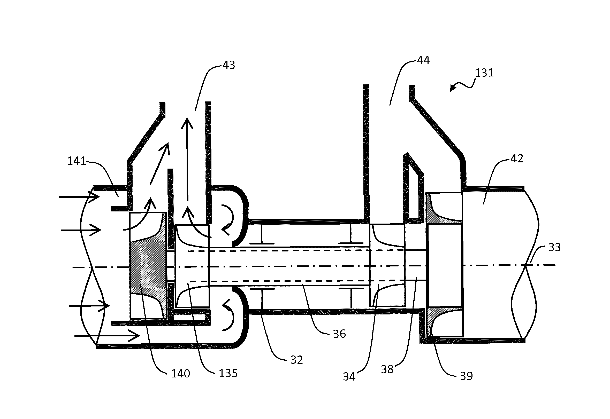
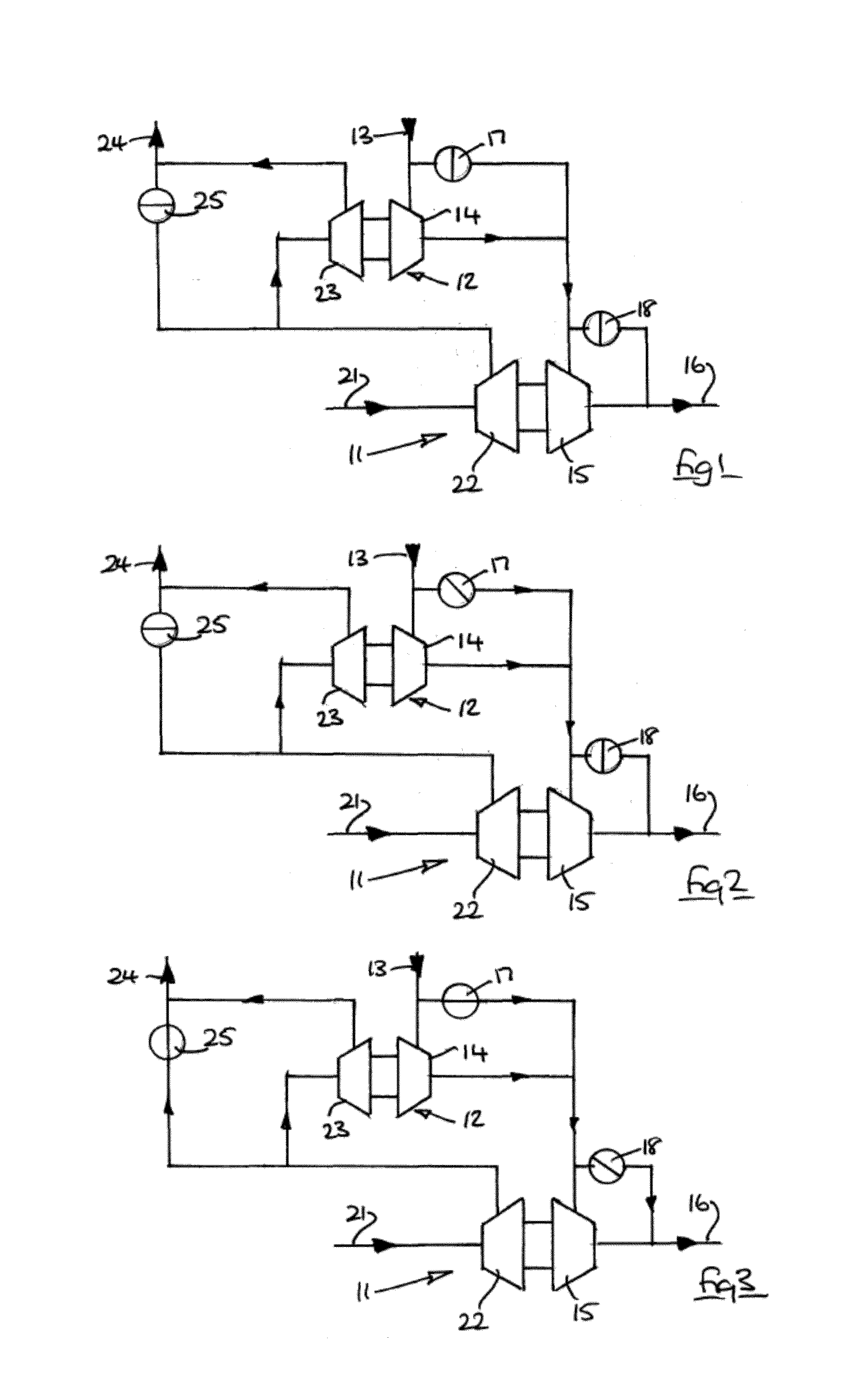
[0033]FIGS. 1-3 illustrate a conventional two-stage turbocharger arrangement having a larger diameter turbine / compressor 11, a small diameter turbine / compressor 12 and an example of an arrangement of passageways and valves, which will now be described.

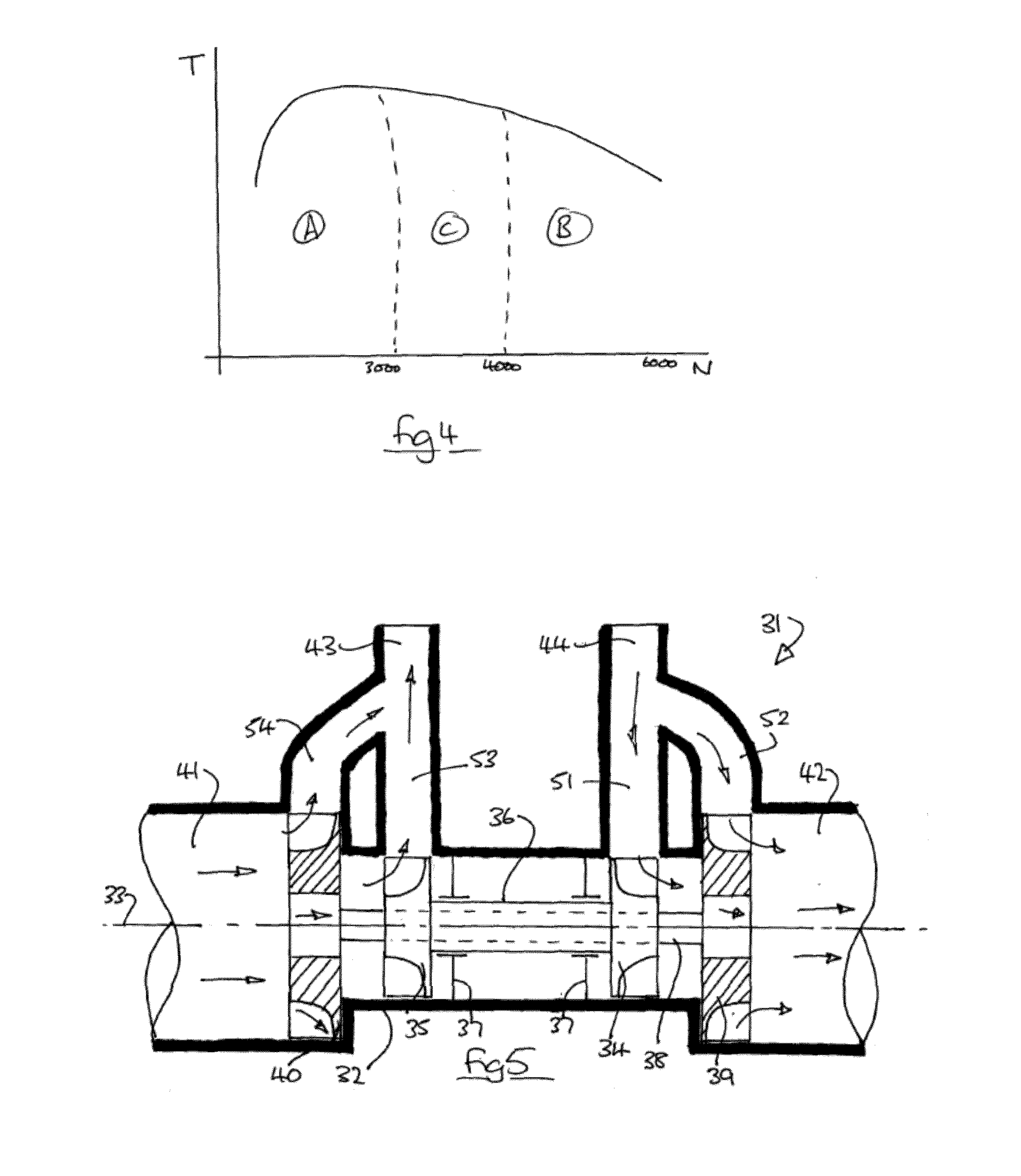
[0034]FIG. 1 illustrates lower engine speed operation, in the range 1000-3000 rpm. Exhaust flow from an engine exhaust manifold 13 passes through the small turbine 14, and then via the large turbine 15 to the exhaust tract 16. Bypass valves 17, 18 are closed. In this engine speed range, the small turbine 14 is effective whereas the large turbine 15 is somewhat ineffective.

[0035]On the compressor side, gas from the inlet tract 21 passes sequentially through the large compressor 22 and small compressor 23 to the engine inlet manifold 24. A relief valve 25 is closed. In this engine speed range, gas compression is mainly generated by the small compressor 23 (which is driven by the small turbine 14).

[0036]FIG. 2 illustrates operation in the...


PUM


Abstract

A turbo pump has a common axis of rotation for a plurality of compressor and turbine wheels. One or more of the turbine and compressor wheels defines a gas passage axially therethrough, said gas passage being associated with another of the turbine and compressor wheels. The arrangement provides a compact multi-stage turbocharger.

Description

FIELD[0001]This invention relates to a multi-stage turbo pump, in particular a multi-stage turbocharger for an internal combustion engine. Aspects of the invention relate to a pump, to an engine and to a vehicle.BACKGROUND[0002]Exhaust driven turbochargers have been used for many years to improve the power and efficiency of internal combustion piston engines, particularly in vehicles. A simple single stage turbocharger comprises an exhaust driven turbine which directly drives a co-axial compressor of inlet gas, thus allowing a greater volumetric charge in each cylinder than would otherwise be the case.[0003]Ideally the exhaust driven turbine would work effectively at all engine speeds and exhaust gas flows, but generally speaking a turbine which is efficient at high engine speeds is somewhat ineffective at low engine speeds (low exhaust gas flow), resulting in the undesirable phenomenon of turbo lag.[0004]Likewise a turbine which is efficient at low engine speeds would likely be lim...

Claims


Application Information

Patent Timeline
IPC IPC(8): F02B37/14F04D27/00
CPCF04D27/005F02B37/14F04D25/024F04D25/16F04D29/284F05D2220/40Y02T10/12F02M26/09F02M26/34F02B37/001F02B37/007F02C6/12F04D29/286F05B2220/40
Inventor ROQUES, OLIVIER
Owner JAGUAR LAND ROVER LTD
Why Eureka
Eureka Blog
Learn More