Hybrid receiver-combustor

a receiver and hybrid technology, applied in the direction of electric generator control, lighting and heating apparatus, machines/engines, etc., can solve the problems of limited resources, only substituting a fraction of the need, fossil fuel power, etc., and achieve the effect of minimising convective losses and minimising convective losses through the apertur

Active Publication Date: 2015-02-26
ADELAIDE RES & INNOVATION PTY LTD
View PDF6 Cites 10 Cited by
  • Summary
  • Abstract
  • Description
  • Claims
  • Application Information

AI Technical Summary

Benefits of technology

[0069]In another mode of operation, the hybrid receiver-combustor may be controlled to use solely the fuel source, wherein the fluidic seal is established to minimise convective losses through the aperture.
[0070]In yet another mode of operation, the hybrid receiver-combustor may be controlled to use the solar source and the fuel source in combination, wherein the fluidic seal is established to minimise convective losses through the aperture while allowing solar radiation to pass through the aperture.

Problems solved by technology

While biomass and waste fuels can partially displace the use of fossil fuels, they are a limited resource and can only substitute a fraction of the need.
Power generation using concentrating solar thermal technologies remains significantly more expensive than conventional, fossil fuel power.
In addition, while solar thermal power allows for thermal storage, it is not cost-effective to provide sufficient storage for periods of extended cloud cover.
Despite its advantages, storage also adds to capital cost, which is a further barrier to implementation.
Such a system typically results in the solar system cooling down during the night and the combustor being turned down (at least partly) during the day.
This results in significant heat losses and inefficiency.
It also requires heat exchangers for each energy source, adding to the capital cost of the combined system.
The percentage of renewable energy that can be achieved by solar-contribution hybrid systems without storage is also limited.
There are, however, various problems and difficulties that confront known hybrid solar and combustion systems in relation to operation for extended periods of time and also thermal shock, some of which are outlined in more detail below.
However, the window is of a configuration which intrudes into the device, thereby limiting the available volume to accommodate the cavity.
Moreover, the presence of a window is problematic as it is increasingly vulnerable to damage as the concentration ratio of the concentrated solar radiation is increased.
At high fluxes, even small particles can cause damage to the surface of the window and lead to a high risk of failure.
This can add significantly to operating and maintenance costs.
Still further, the use of the window requires that operation of the hybrid solar and combustion system be interrupted to clean the window, thereby preventing continuous, long-term operation of the system using both combustion and solar energy sources.
While this arrangement would allow the system to operate in both modes at the same time, it would almost certainly experience the problems referred to above associated with the window in U.S. Pat. No. 4,602,614.
A further problem likely to be encountered with the arrangement disclosed in U.S. Pat. No. 5,884,481, when in the solar operating mode, is that of thermal shock arising from rapid variations in the intensity of available solar radiation.
A rapid change in heat-flux can generate high stresses in the heat exchange materials, the management of which can incur significant penalties.
By way of example, the use of more exotic, high temperature materials would almost certainly increase costs.
However, because the device has separate zones for the collection of solar energy and combustion energy, it is likely that the device will need to be relatively large and will also be prone to higher heat losses.
Furthermore, the device does not have the capacity to mitigate against thermal shock.

Method used


Image

  • Hybrid receiver-combustor
  • Hybrid receiver-combustor
  • Hybrid receiver-combustor

Examples


first embodiment

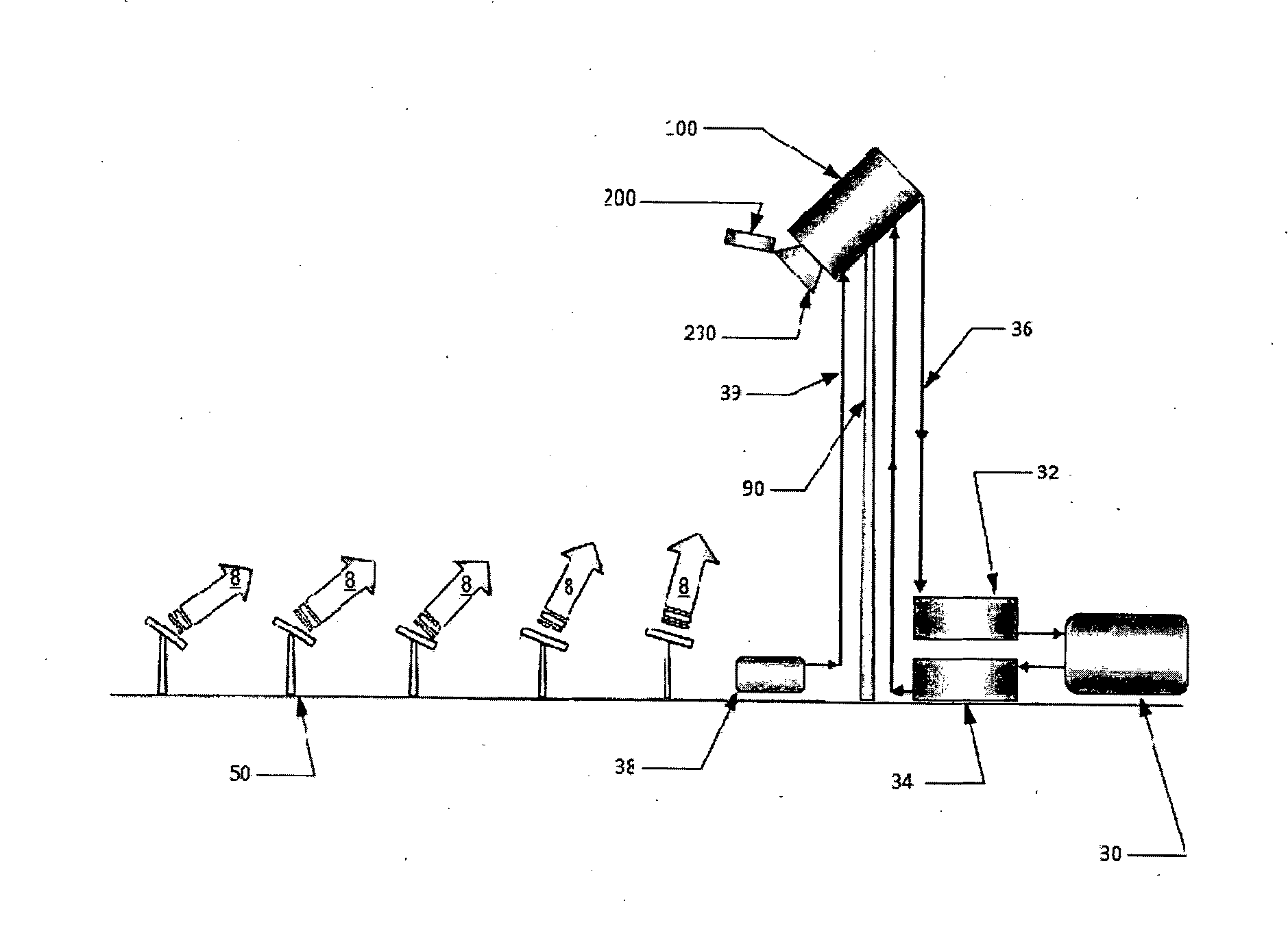
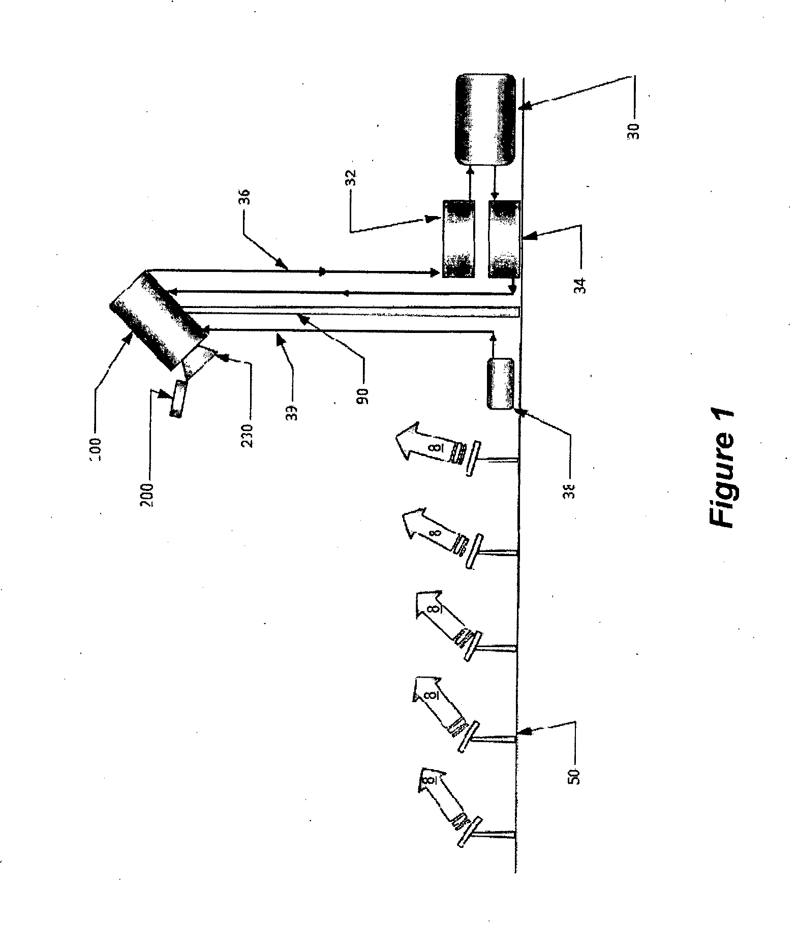
[0094]FIG. 3 shows a hybrid receiver-combustor 100 according to the invention in a diagrammatic cross-sectional view. The hybrid receiver-combustor 100 includes a vessel 110 that acts both as a combustion furnace and as a solar receiver, and a plurality of burners 180 for combusting an oxidant stream, such as an air stream, and a fuel stream. The vessel or furnace 110 includes a casing 120 defining a cavity 125 having an aperture 130 for receiving the concentrated solar radiation referred to above. The cavity 125 provides a chamber defining a zone 126 which can function as a combustion zone for production of heat energy through a combustion process using the fuel and into which concentrated solar radiation can be received from the solar source through the aperture 130.

[0095]Each burner 180 is arranged in fluid communication with the cavity 125 so as to direct a flame into the cavity 125. The flame 182 creates a flame zone and also generates an exhaust gas 184.

[0096]A heat energy abs...

second embodiment

[0133]The operation of the invention shown in FIG. 4 will now be described while providing further, detail as to the components of the embodiment.

[0134]The concentrated solar radiation enters the cavity 125 through the aperture 130. The aperture 130 is advantageously fitted with a concentrating parabolic concentrator (CPC) 230.

[0135]The inside of the cavity 125 is lined with tubes to convey the heat-transfer fluid, which is to be heated. The heat-transfer fluid can be any gaseous or liquid fluid, such as molten salt or steam, in the case of power generation applications. Non-power generating applications include a mixture of stream and carbonaceous particles to be heated for the purpose of gasification, but this list is not intended to be exhaustive. Small gaps are required between the tubes 192 to allow for thermal expansion.

[0136]A ring of burners 180 are introduced from the opposite end of the chamber to the aperture, to fire toward the aperture, in the opposite general direction...

fourth embodiment

[0159]In this fourth embodiment, the vessel 110 comprises a side section 194, a top section 195 and a bottom section 196. The aperture 130 is incorporated in the side section 195 and the burner 180 is incorporated in the bottom section 196, as shown in FIG. 12. With this arrangement, the burner 180 is arranged to fire generally transversely of solar radiation entering the cavity 125 through the aperture 130 through the aperture to thereby impinge upon the incoming solar radiation.

[0160]The fourth embodiment of the hybrid receiver-combustor 100 is oriented such that the aperture 130 faces the solar source and thereby the portion of the side section 194 which incorporates the aperture constitutes the front end of the hybrid receiver-combustor.

[0161]In the embodiments which have been described and illustrated, the heat energy absorber is configured as a heat-transfer fluid heat exchanger. Other arrangements are possible, as outlined below.

[0162]One such other arrangement involves appli...


PUM


Abstract

A hybrid receiver-combustor (100) for capturing heat energy from a solar source and a fuel source. The hybrid receiver-combustor (100) includes a vessel (110) for acting both as a combustion furnace and as a solar receiver, and a plurality of burners (180) for combusting an oxidant stream, such as an air stream, and a fuel stream. The vessel (110) includes a casing (120) defining a cavity (125) having an aperture (130) for receiving the concentrated solar radiation from the solar source. The cavity (125) provides a chamber defining a zone (126) which can function as a combustion zone for production of heat energy through a combustion process using the fuel and into which concentrated solar radiation can be received from the solar source through the aperture (130). A heat energy absorber (190) configured as a heat exchanger is provided to receive heat energy from concentrated solar radiation entering the cavity (125) through the aperture (130) and from combustion within the cavity. A fluidic seal system (135) is associated with the aperture (130) and is operable to establish a fluidic seal to restrict fluid flow through the aperture (130) during the combustion process. The fluidic seal comprises exhaust gas from the combustion process within the cavity (125).

Description

FIELD OF THE INVENTION[0001]The present invention relates to a hybrid receiver-combustor for capturing heat energy from a solar source and a fuel source. In particular, the hybrid receiver-combustor is adapted to capture heat energy from a solar source and accommodate combustion to generate heat from a fuel source. The invention has been devised particularly, although not necessarily solely, for use in either power generation or chemical processing. The invention also relates to a method of operating a hybrid receiver-combustor, as well as a system and method for generation of electrical power.BACKGROUND[0002]The following discussion of the background art is intended to facilitate an understanding of the present invention only. The discussion is not an acknowledgement or admission that any of the material referred to is or was part of the common general knowledge as at the priority date of the application.[0003]Heat is required in many applications including power generation and che...

Claims


Application Information

Patent Timeline
Patent Type & Authority Applications(United States)
IPC IPC(8): F03G6/06F01D15/10F24J2/04F24S20/20
CPCF03G6/06F01D15/10F24J2/04F03G6/00Y02E10/46F24S10/00F24S20/20Y02E10/44Y02E10/40F03G6/068
Inventor NATHAN, GRAHAM J.DALLY, BASSAMASHMAN, PETERSTEINFELD, ALDO
Owner ADELAIDE RES & INNOVATION PTY LTD
Why Eureka
Try Eureka