
High resolution absolute encoder

a technology of absolute encoder and encoder, which is applied in the direction of galvano-magnetic hall-effect devices, instruments, galvano-magnetic devices, etc., can solve the problems of incremental encoders, add complexity to the search procedure, delay the first operation of the machine, etc., and achieves simple structure, reduced cost, and reduced complexity

Active Publication Date: 2015-03-12
SERVOSENSE SMC
View PDF6 Cites 21 Cited by
  • Summary
  • Abstract
  • Description
  • Claims
  • Application Information

AI Technical Summary

Benefits of technology

The invention provides an absolute encoder device that is simpler, smaller, and cheaper but with high absolute resolution. It uses commercially available sensors without the need for an additional patterned track. The device has a rotating disc section with a pattern of properties that form a Gray code, which ensures accurate position measurement during disc rotation. The device has two sensors that produce normalized signals, which are compared and the signal with the closest value to the threshold is selected. This results in a high resolution position value of the rotating disc. The invention is a high resolution absolute encoder that is easy to use, cost-effective, and can be implemented with off the shelf components.

Problems solved by technology

This search procedure adds complexity to the system, and delays the first operation of the machine.
In many cases, a machine builder would have preferred to use an absolute encoder, but makes use of an incremental encoder due to the higher cost of presently available absolute encoders.
The absolute resolution of an absolute encoder device is limited by the number of sensors.
This results in higher complexity, size and cost of the device.
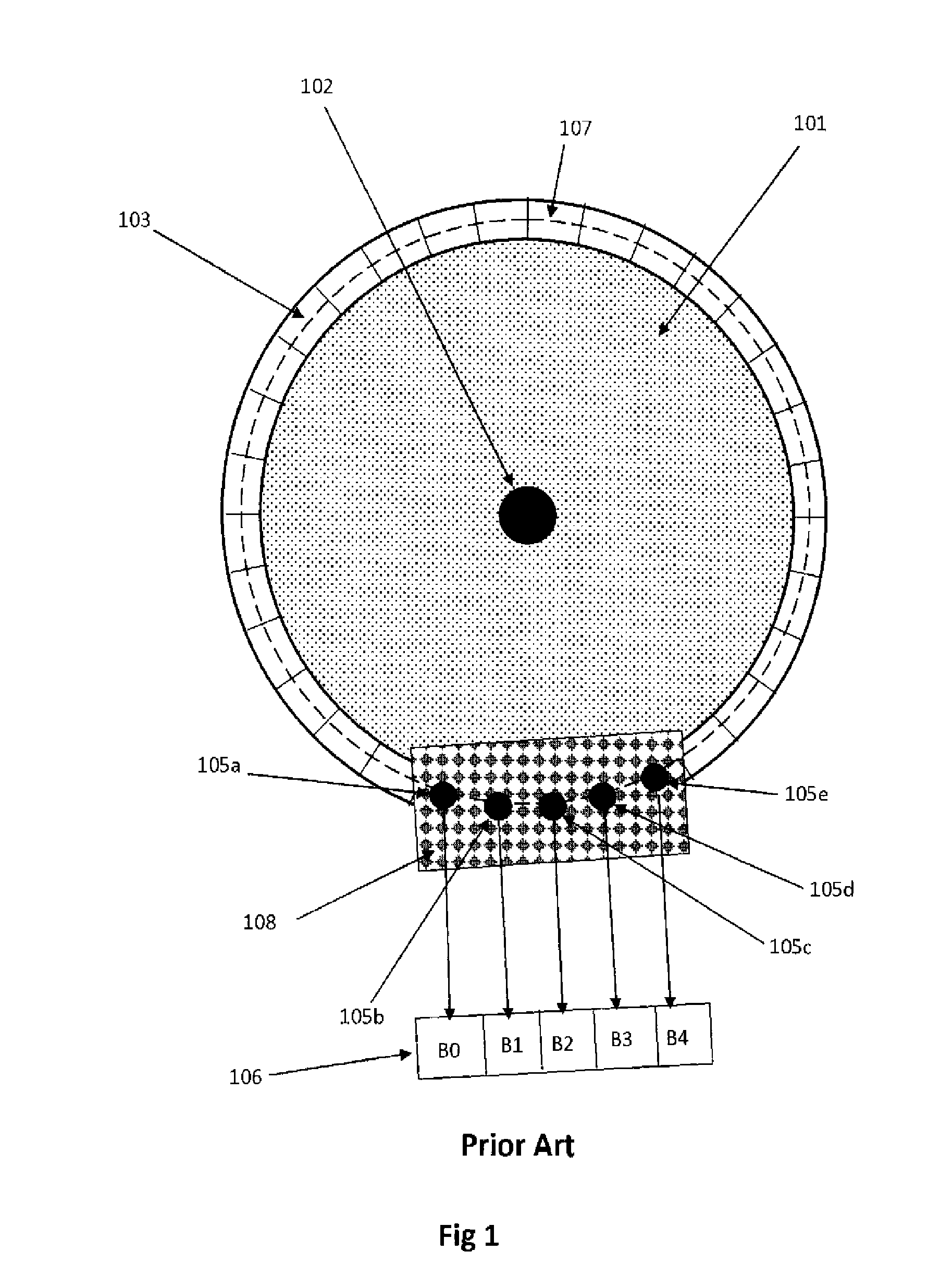
A first drawback of this prior art embodiment is the requirement that the sensors used to measure the absolute position must be placed at angular distances equal to a sector's angular size.
In that case commercially available sensors cannot be used, and custom sensors, integrated on one chip, must be used.
This implementation is not practical, due to the high cost and the lack of modularity.
If magnetic sensors are considered, the design of small size integrated device is even more complex and expensive.
A second drawback of this prior art embodiment is the fact that resolution is limited.
Due to practical considerations on the size of the sensors and the size of the sectors, the number of sectors is limited, and thus also the encoder resolution.
This results in increased complexity and cost of the encoder.
Villaret, while eliminating the first drawback mentioned above, however still suffers from a limited resolution, due to practical limitations in the size of the sectors.

Method used


Image

  • High resolution absolute encoder
  • High resolution absolute encoder
  • High resolution absolute encoder

Examples


Embodiment Construction

[0053]In the following detailed description, numerous specific details are set forth in order to provide a thorough understanding of the invention. However, it will be understood by those skilled in the art that the present invention may be practiced without these specific details. In other instances, well-known methods, procedures, and components have not been described in detail so as not to obscure the present invention.

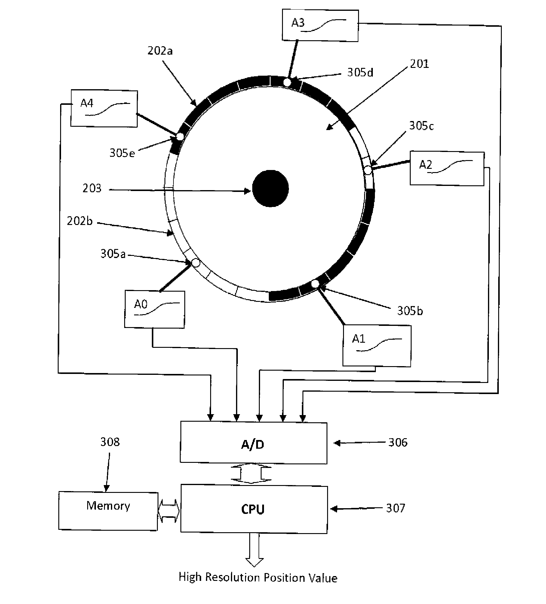
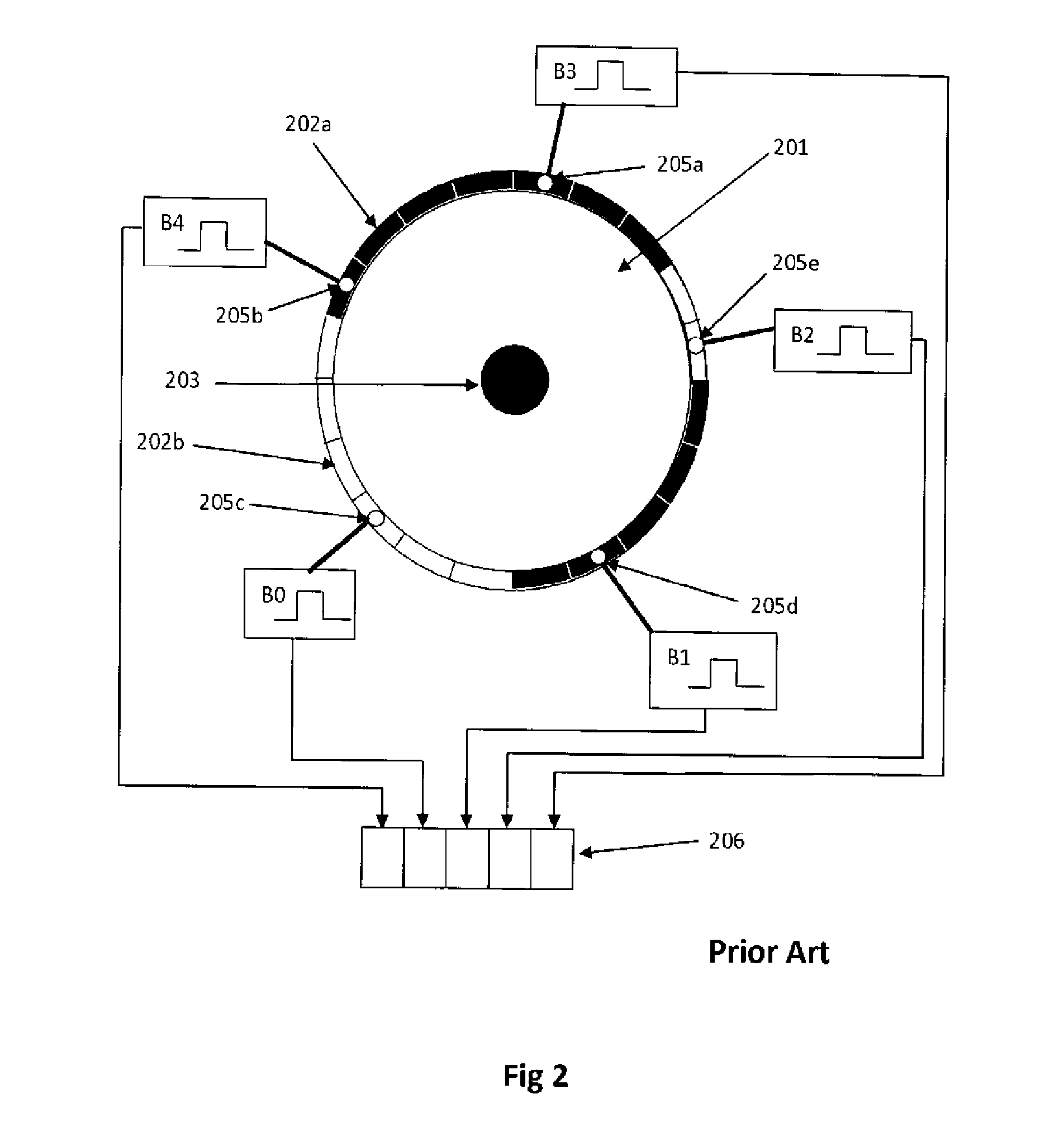
[0054]In FIG. 3 there is shown an encoder arrangement, according to the present invention, providing an improvement to Villaret, wherein the S=5 sensors 205a-205e of FIG. 2 providing digital signals, are replaced by S=5 analog sensors 305a-305e; the S=5 analog sensors generate analog signals A0-A4. These analog signals are then digitized by an analog to digital converter unit 306, and then transferred to a Processor unit 307. It will be shown that this new arrangement provides high resolution without the need of an additional incremental encoder.

[0055]In FIG. 4 th...


PUM


Abstract

The device to measure the absolute rotation angle of a rotating shaft includes a rotating disc, fixed to the shaft. A group of permanent magnets of different sizes and polarities is disposed on a circular track. Further, a group of Hall sensors, fixed to a static part of the device, are disposed on a circular path, in proximity of the rotating disc magnets tracks, and generate electric signals proportional to the strength of the magnetic field produced by the magnets in proximity. The signs of these electric signals are used to calculate a code characteristic of a low resolution absolute angular position. Two analog signals are associated to the obtained code, according to a pre-defined table. The associated analog signal having the closest value to zero is used as an entry to a pre-recorded table containing the correspondent angular position of the shaft.

Description

CROSS REFERENCE TO RELATED APPLICATIONS[0001]The present application is a non-Provisional utility patent application, which claims the benefit of U.S. Provisional Application 61 / 580,668, filed 28 Dec. 2011, the disclosure of which is incorporated herein by reference.FIELD OF THE INVENTION[0002]The present invention relates to devices for determining the amount of displacement and the position of a moving body and, in particular, to encoder devices (encoders).BACKGROUND OF THE INVENTION[0003]Encoders are used to measure the angular position of a rotating element, or the relative displacement of sliding elements. They are typically used in control systems, often referred to as servo systems, where a motion controller is used to make a moving element follow a precise desired path. For that purpose, encoder devices include an electronic interface which allows their connection to a motion controller.[0004]Encoders may be of two types, rotary and linear. Rotary encoders are designed to me...

Claims


Application Information

Patent Timeline
Patent Type & Authority Applications(United States)
IPC IPC(8): G01D5/12G01B7/30G01B7/00
CPCG01D5/145G01D5/24476G01D5/2455
Inventor VILLARET, YVES
Owner SERVOSENSE SMC
Learn More