Fixed-array anisotropic conductive film using conductive particles with block copolymer coating

a technology of anisotropic conductive film and copolymer coating, which is applied in the direction of conductive materials, solid-state devices, textiles and paper, etc., can solve the problems of reducing the likelihood of encapsulation desorption and the complexity of the assembly of the acf layer, and achieves the effect of superior insulation properties of conductive particles, easy removal, and reduced minimum bonding spa

Inactive Publication Date: 2015-03-12
TRILLION SCI INC
View PDF2 Cites 5 Cited by
  • Summary
  • Abstract
  • Description
  • Claims
  • Application Information

AI Technical Summary

Benefits of technology

[0013]It has been found that block copolymers, particularly those comprising a block that is incompatible with the adhesive composition, provided superior insulation properties for conductive particles even at their aggregated states and yet can be easily removed at mild bonding temperature/pressure conditions (for example, 80 to 200° C. and ≦3 MPa) to form true ohm contact between the conductive particles and the electrodes in the connection area. Block copolymers are also readily soluble or dispersible in common solvents and encapsulation of the conductive particles may be achieved efficiently by, for example, addition of non-solvents/additives or change of temperature to form a protective thermoplastic elastomer layer or particulates on the surface of conductive particles. Also, the ACFs comprising conductive particles encapsulated with the block copolymer showed significantly lower minimum bonding space and significant improvements in the adhesive properties including the thermal shock and HHHT (high temperature, high humidity) environmental stability. In some cases, the use of such insulated conductive particles also reduces the microvoid content and improves reliability and fatigue resistance. Not to be bound by theory, the block copolymer may function as an impact modifier or low profile additive in the adhesive matrix. The incompatibility between the block copolymer incompatible segment and the adhesive composition reduces the likelihood of desorption of the encapsulation layer from the conductive particles during processing and storage. And, the thermoplas

Problems solved by technology

The incompatibility between the block copolymer incompatible segment and the adhesive composition reduces the likelihood of desorption of the encapsulation layer from the conductive particles during processing an

Method used


Image

  • Fixed-array anisotropic conductive film using conductive particles with block copolymer coating

Examples


Embodiment Construction

[0016]U.S. Published Applications 2010 / 0101700 2012 / 0295098 and 2013 / 0071636 to Liang et al. are incorporated herein in their entirety by reference.

[0017]Any of the conductive particles previously taught for use in ACFs may be used in practicing this disclosure. Gold coated particles are used in one embodiment. In one embodiment, the conductive particles have a narrow particle size distribution with a standard deviation of less than 10%, preferably less than 5%, even more preferably less than 3%. The particle size is preferably in the range of about 1 to 250 μm more preferably about 2-50 μm even more preferably about 3-10 μm. In another embodiment the conductive particles have a bimodal or a multimodal distribution. In another embodiment, the conductive particles have a so called spiky surface. The size of the microcavities and the conductive particles are selected so that each microcavity has a limited space to contain only one conductive particle. To facilitate particle filling an...


PUM

PropertyMeasurementUnit
Temperatureaaaaaaaaaa
Lengthaaaaaaaaaa

Abstract

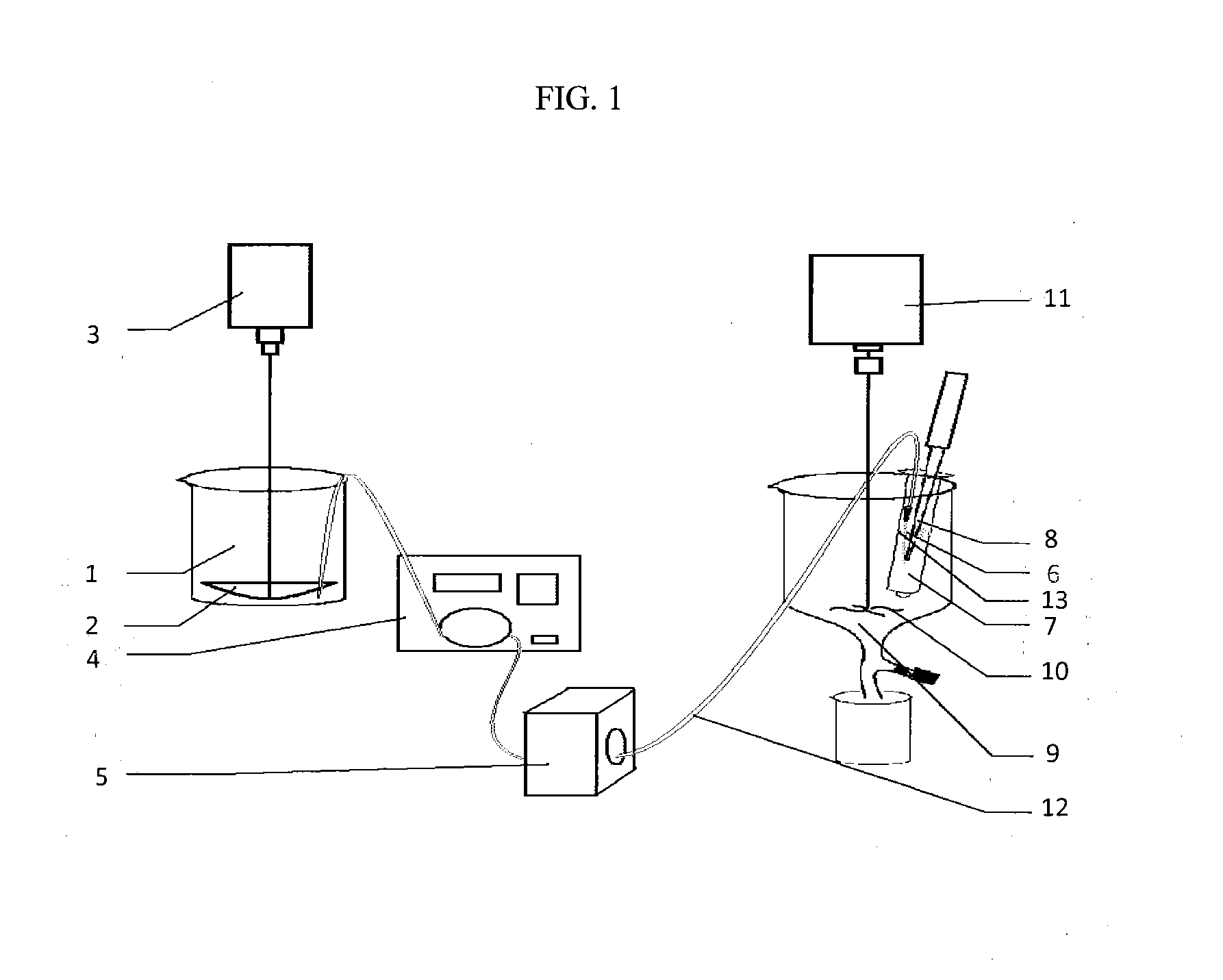
Structures and manufacturing processes of an ACF array and more particularly a non-random particles are transferred to the array of microcavities of predetermined configuration, shape and dimension. The manufacturing process includes fluidic filling of conductive particles surface-treated with a block copolymer composition onto a substrate or carrier web comprising a predetermined array of microcavities. The thus prepared filled conductive microcavity array is then over-coated or laminated with an adhesive film.

Description

BACKGROUND[0001]1. Field[0002]This invention relates generally to structures and manufacturing methods for anisotropic conductive films (ACF). More particularly, this invention relates to structures and manufacturing processes for an ACF having improved resolution and reliability of electrical connections in which the conductive particles are treated with a composition comprising a two-phase block copolymer type of elastomer comprising a segment that is incompatible with the ACF adhesive.[0003]2. Description of the Related Art[0004]Anisotropic Conductive Film (ACF) is commonly used in flat panel display driver integrated circuit (IC) bonding. A typical ACF bonding process comprises for example, a first step in which the ACF is attached onto the electrodes of the panel glass; a second step in which the driver IC bonding pads are aligned with the panel electrodes; and a third step in which pressure and heat are applied to the bonding pads to melt and cure the ACF within seconds. The c...

Claims


Application Information

Patent Timeline
IPC IPC(8): H01B7/40H01B3/30H01B3/28H01B3/44H01B7/00H01B7/02
CPCH01B7/40H01B7/0009H01B3/307H01B3/28H01B3/447H01B7/02H01B3/442H05K3/323H01L2224/2949H01L2224/271H01L2224/2939H01L2224/29455H01L2224/29439H01L2224/29447H01L24/16H01L24/27H01L24/29H01L24/32H01L2224/16227H01L2224/2929H01L2224/29387H01L2224/29393H01L2224/29411H01L2224/29499H01L2224/32227H01L2224/83851H01L2224/29444H01L2224/81903H01L2224/29424H01L2224/29469H01L2224/29423H01L2224/2946H01L2224/16225H05K2201/0221H01L2924/12042H01L2924/12044H01L2924/12041Y10T428/2438H01L2924/01006H01L2924/00014H01L2924/00H01L24/83H05K1/0213
Inventor LIANG, RONG-CHANGSUN, YUHAOAN, ZHIYAO
Owner TRILLION SCI INC
Why Eureka
Try Eureka