
System and Method for Building and Maintaining Stable Sand Beach and Shoreline Profiles and for Controlling Beach or Riparian Erosion

a sand beach and shoreline profile technology, applied in the direction of groynes, construction, marine site engineering, etc., can solve the problems of inability to maintain stable sand beach and shoreline profile, so as to eliminate extra cost and logistical problems, and eliminate buoyancy

Active Publication Date: 2015-03-19
MESSINA MARIO L
View PDF18 Cites 4 Cited by
  • Summary
  • Abstract
  • Description
  • Claims
  • Application Information

AI Technical Summary

Benefits of technology

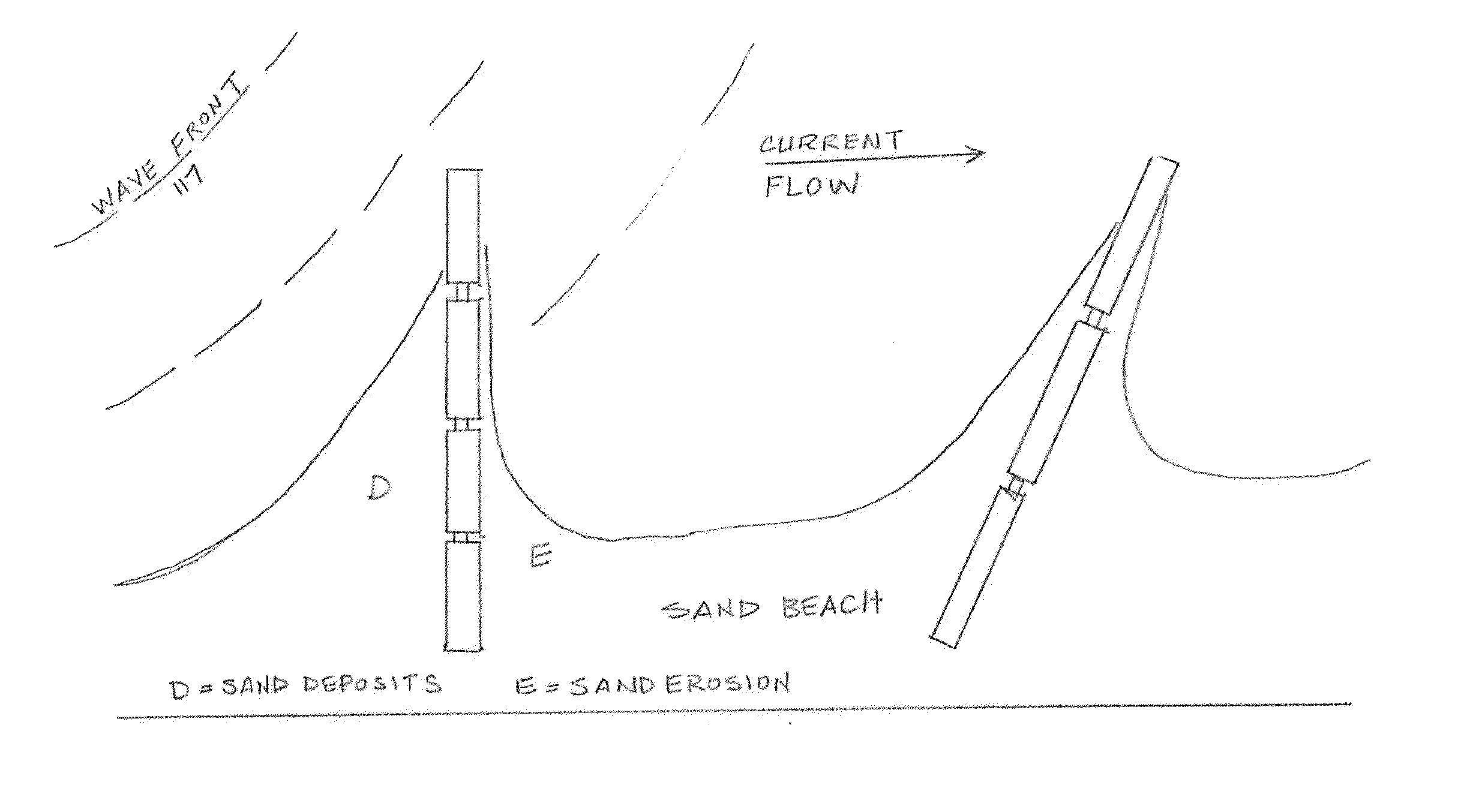
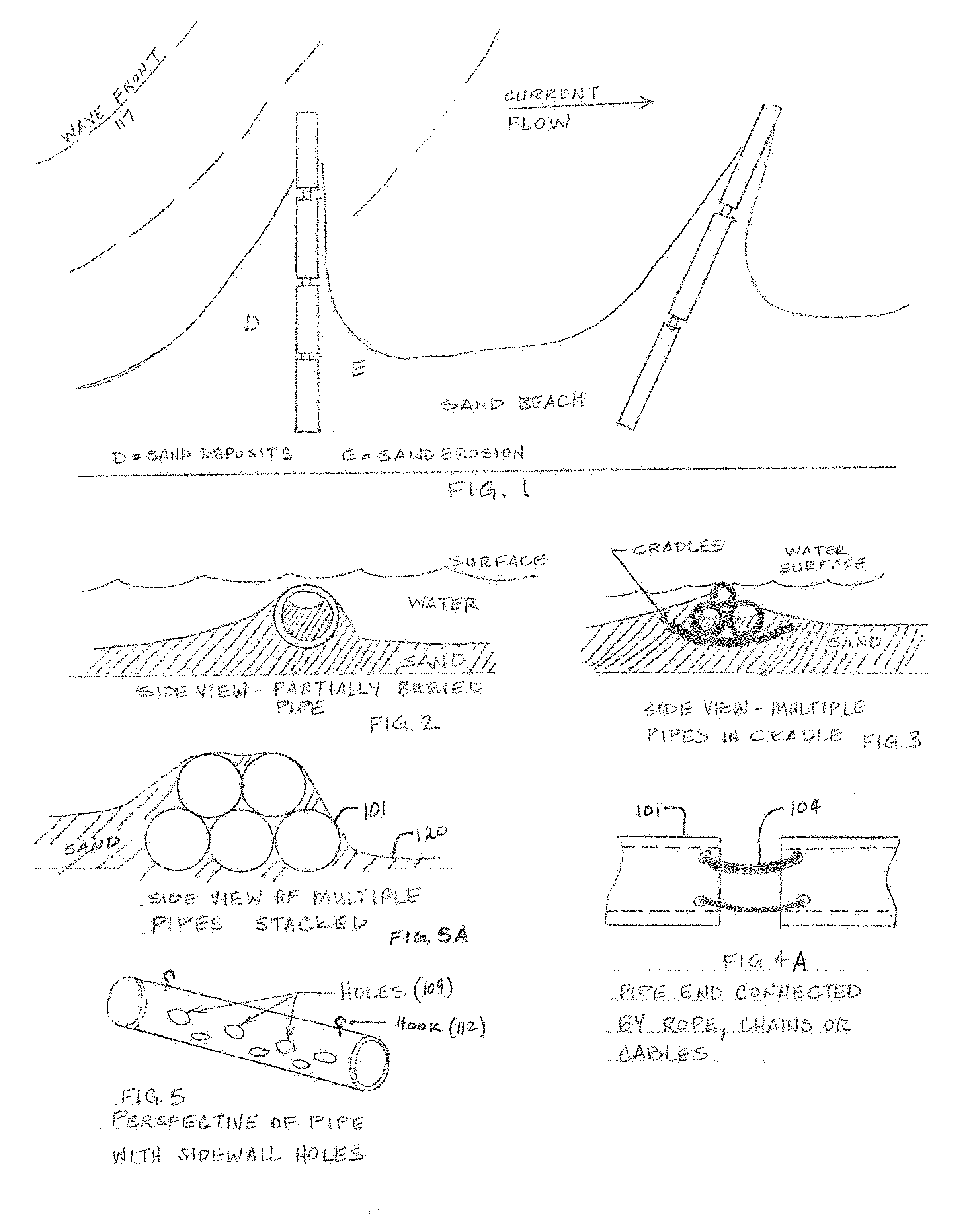
The invention is a unique system of plastic pipes that can be used to slow down the current of sand-carrying sea bottom animals and plants. The pipes are designed to be flexible, durable, and cost-effective. They can be easily moved or added onto and can be left unfilled to provide buoyancy. The pipes are installed at a shallow depth in the seafloor and act as a speed bump to slow down the bottom currents. The system can be easily removed and moved to another location if needed. The pipes have small to large holes drilled in them before placement, which allows them to become filled with water and sand, stabilizing them within the confines of the piles or cradles. This eliminates the need to fill the pipes with sand or concrete after placement. Overall, the invention provides a safe and effective solution for protecting the ecology of the sea bottom and for promoting the growth of a low-profile, delta-like platform.

Problems solved by technology

Such erosion can result from normal tidal action, severe wave action arising from storms and hurricanes, and from simple inundation due to rising water levels.
When this outflow of fresh and brackish water from land and estuaries combines with tidal flows into and out of the estuaries and bays into the gulfs or seas, it can cause instability in the water flow along the near-shore on both sides of inlets that can extend for great distances along the coast line.
Wind-generated waves will also cause erosion or accretion of sand onto the beach or near-shore environments.
However, this method of beach restoration has proven to be somewhat temporary and very costly.
It can also be harmful to the environment by having a negative effect on the benthonic life on the bottom.
Despite being unnatural and eyesores, such structures have been successful in preserving or protecting property on the landside of the structure, however, they often accelerate the beach sand erosion process due to the fact that the full force of the incoming wave energy is not dissipated, particularly storm waves.
The velocity of water energy contained in the wave does not allow time for the sand to drop out under the force of gravity and accrete on the beach.
These structures can also have a negative impact by causing erosion on adjacent beaches.
Construction permits for such structures are difficult to obtain where they may impact sea turtle nesting grounds.
In other words, sand is accreted on the upside beaches, and downside beaches become deprived of their sand supply.
The disadvantage of groins is they are unnatural eyesores, they can be dangerous to surfers and swimmers and they can have a negative impact on turtles and other sea life.
Plastic mesh groins are not durable and can be subject to vandalism.
Geo-textile tubes are disadvantageous because they are often expensive eyesores that are time consuming and difficult to install.
They are subject to breakage and vandalism.
Using concrete fill makes the geo-textile tubes more durable, but also rigid, permanent fixtures that become very expensive to remove if they did not work.
Being rigid structures they may break during high magnitude storm events and thus less effective and may become an environmental hazard.

Method used


Image

  • System and Method for Building and Maintaining Stable Sand Beach and Shoreline Profiles and for Controlling Beach or Riparian Erosion
  • System and Method for Building and Maintaining Stable Sand Beach and Shoreline Profiles and for Controlling Beach or Riparian Erosion
  • System and Method for Building and Maintaining Stable Sand Beach and Shoreline Profiles and for Controlling Beach or Riparian Erosion

Examples


Embodiment Construction

[0038]A portion of the disclosure of this patent document contains material which is subject to copyright protection. The copyright owner has no objection to the facsimile reproduction by anyone of the patent document or the patent disclosure as it appears in the Patent and Trademark Office patent file or records, but otherwise reserves all copyright rights whatsoever.

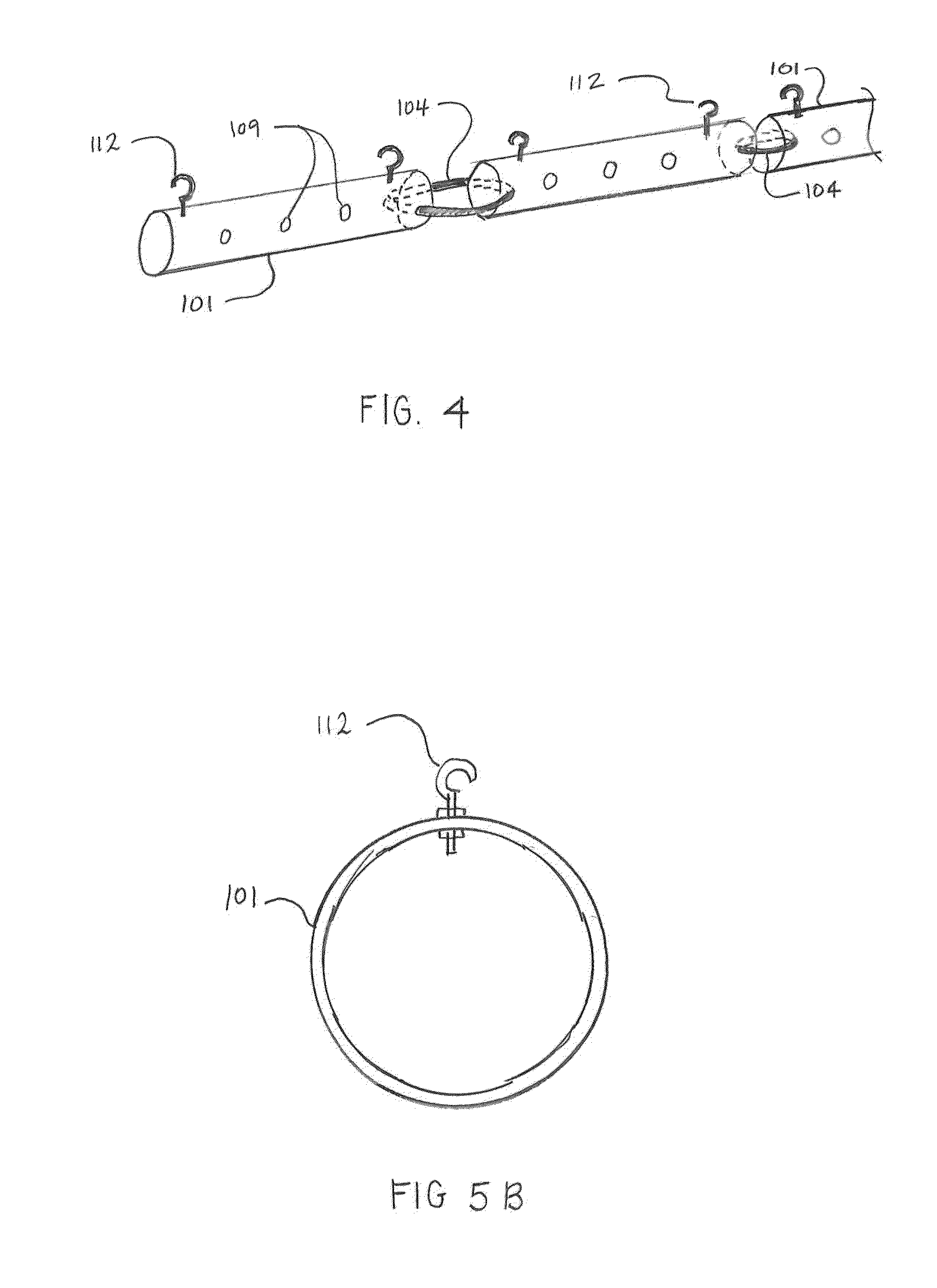
[0039]The invention uses man-made synthetic, normally plastic-type pipes (101) with varying flexibility depending on composition and thickness of the pipe (101). The plastic pipe (101) composition is chosen by the coastal engineering professional for durability and ability to withstand the corrosive effects of seawater (102). The pipes (101) used in the design shall have various lengths, diameters and colors as necessary to achieve the design intent. These pipes (101) are to be self-filling by means of large holes (109) drilled into them before positioning on the seafloor (103) to allow sand to fill the interior space ...


PUM


Abstract

A method of building up and maintaining beach sediment, building and changing beach profiles, and controlling beach erosion that uses a series of varying diameter plastic pipes joined to obtain various lengths, laid parallel and on top of each other and situated perpendicular or at various angles to the shoreline. The pipes act to slow bottom currents and promote sand accretion in and around the pipes thereby stabilizing shoreline profiles and controlling beach erosion. The pipes are held together by cables or in a “cradle” to help stabilize the pipes on the sea bottom. Certain pipes have pre-drilled holes of various diameters through their sidewalls to allow in-flow of sand-carrying water such that the pipes become filled with sand acting to stabilize the pipes. Pipe diameter sizes are selected as necessary to accomplish most efficient sediment accumulation around the pipe structures.

Description

PRIORITY CLAIM[0001]This application is a Non-Provisional U.S. Patent Application claiming benefit of U.S. Provisional Patent Application No. 61 / 871,223 filed Aug. 28, 2013, which is incorporated herein by reference in its entirety.FIELD OF THE INVENTION[0002]The present invention relates to building and maintaining stable sand beach or other riparian soil profiles along shorelines of oceans, seas, gulfs, lakes, rivers or streams and, more specifically, to a system and method that uses a series of plastic pipes, of varying composition, thickness and flexibility, strung together and placed along the bottom from the existing shore to a point underwater and offshore. The pipe-string structures are intended to slow down sand-carrying bottom currents such that erosion is inhibited and sand accretion is promoted and / or stabilized.PRIOR ART AND BACKGROUND OF THE INVENTION[0003]Coastal beach erosion is defined by actual removal of sand or other soil from a beach and depositing it offshore, ...

Claims


Application Information

Patent Timeline
Patent Type & Authority Applications(United States)
IPC IPC(8): E02B3/12
CPCE02B3/129E02B3/04Y02A10/00E02B3/06
Inventor MESSINA, MARIO L.
Owner MESSINA MARIO L
Learn More