Method of forming semiconductor structure

a technology of semiconductor structure and semiconductor structure, which is applied in the direction of semiconductor devices, basic electric elements, electrical appliances, etc., can solve the problems of reducing and achieve the effect of improving the performance of the devi

Inactive Publication Date: 2015-03-19
UNITED MICROELECTRONICS CORP
View PDF7 Cites 17 Cited by
  • Summary
  • Abstract
  • Description
  • Claims
  • Application Information

AI Technical Summary

Benefits of technology

[0006]Accordingly, the present invention provides a method of forming a semiconductor structure, by which the conventional metal residues are not observed so that the performance of the device can be effectively improved.

Problems solved by technology

In such case, metal residues remain in the dishing and the performance of the device is therefore decreased.

Method used


Image

  • Method of forming semiconductor structure
  • Method of forming semiconductor structure
  • Method of forming semiconductor structure

Examples


first embodiment

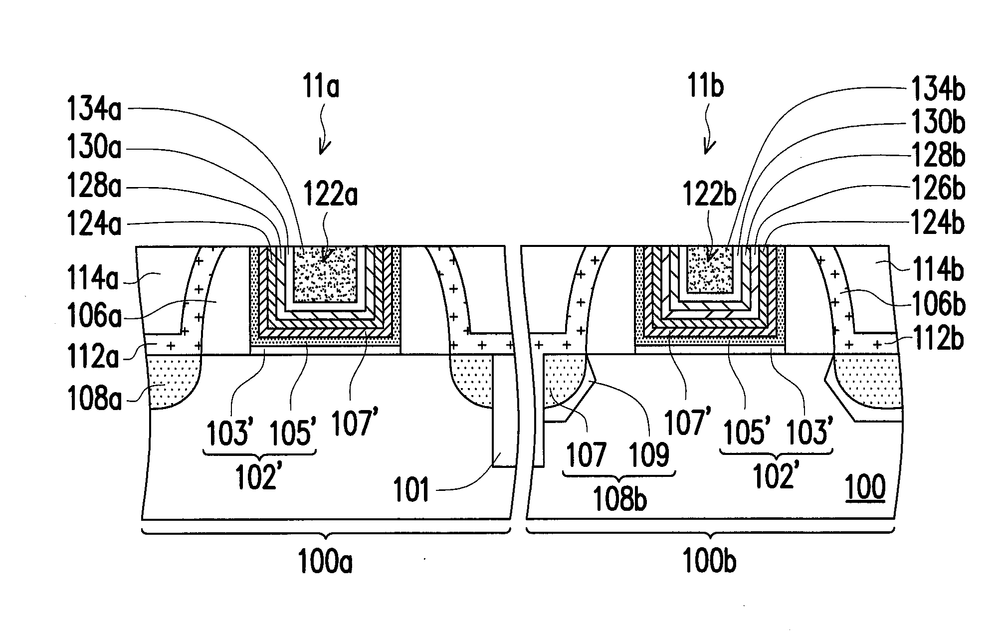
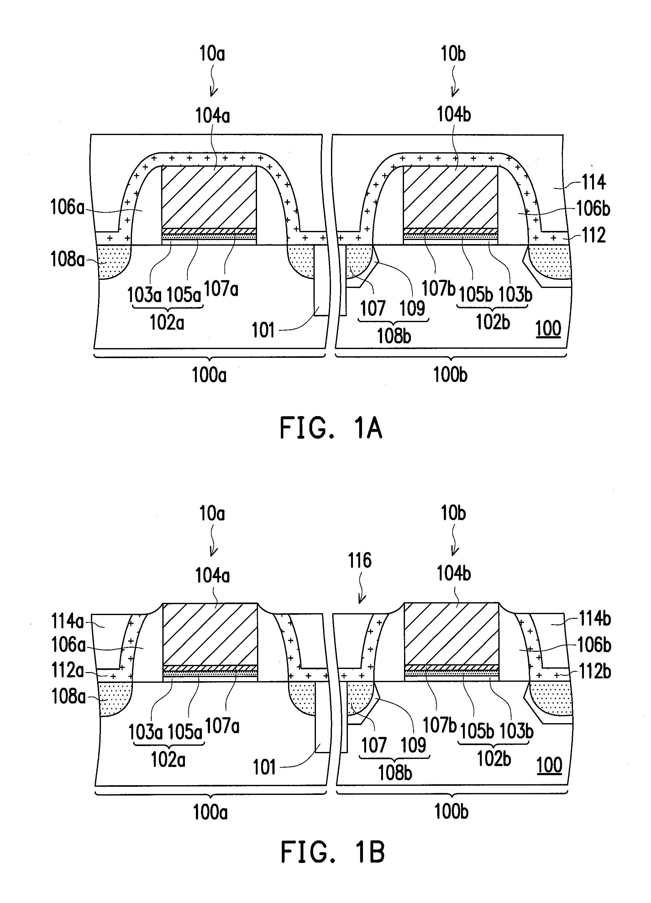
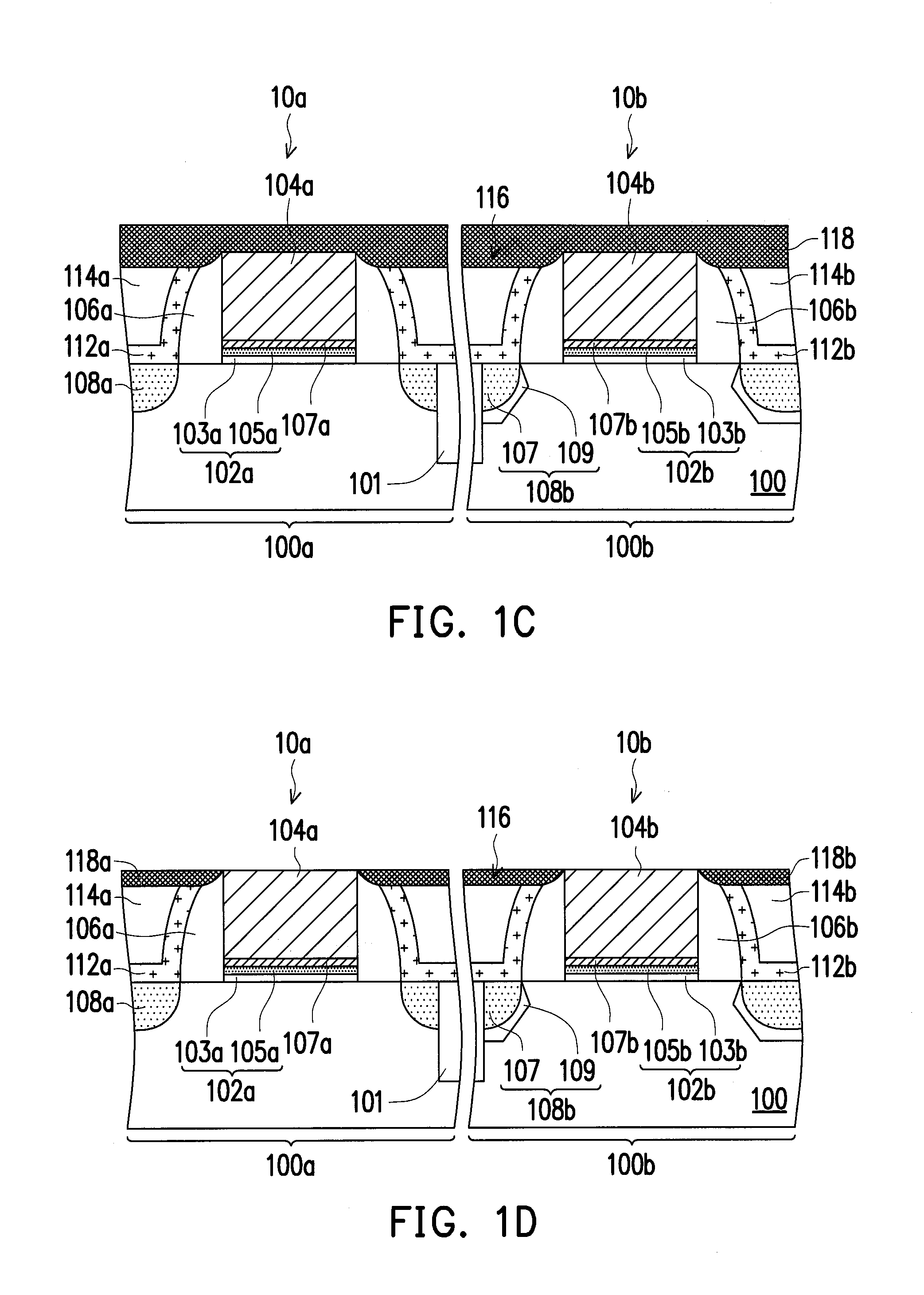
[0025]FIG. 1A to FIG. 1H are schematic cross-sectional views illustrating a method of forming a semiconductor structure according to a first embodiment of the present invention. In this embodiment, the method of the invention is integrated with the “high-k first” process for illustration.

[0026]Referring to FIG. 1A, at least one gate structure is formed on a substrate 100. The substrate 100 can be a semiconductor substrate, such as a silicon substrate. In this embodiment, the substrate 100 has a first area 100a and a second area 100b, and gate structures 10a and 10b are respectively formed in the first and second areas 100a and 100b, but the present invention is not limited thereto. At least one shallow trench isolation (STI) structure 101 is formed in the substrate 100 between the gate structures 10a and 10b for providing electrical isolation. The first and second areas 100a and 100b are for forming semiconductor devices with different conductivity types. In an embodiment, the first...

second embodiment

[0043]The second embodiment is similar to the first embodiment. The difference between first and second embodiments is described in the following, and the similarities are not iterated herein.

[0044]FIG. 2A to FIG. 2G are schematic cross-sectional views illustrating a method of forming a semiconductor structure according to a second embodiment of the present invention.

[0045]Referring to FIG. 2A, at least one gate structure is formed on a substrate 100. The substrate 100 has a first area 100a and a second area 100b, and gate structures 12a and 12b are respectively formed in the first and second areas 100a and 100b. At least one STI structure 101 is formed in the substrate 100 between the gate structures 10a and 10b for providing electrical isolation. The first and second areas 100a and 100b are for forming semiconductor devices with different conductivity types. In an embodiment, the first area 100a is for forming an N-type device, and the second area 100b is for forming a P-type devi...


PUM


Abstract

A method of forming a semiconductor device is disclosed. A gate structure is formed on a substrate. The gate structure includes a dummy gate and a spacer at a sidewall of the dummy gate. A dielectric layer is formed on the substrate outside of the gate structure. A metal hard mask layer is formed to cover tops of the dielectric layer and the spacer and to expose a surface of the gate structure. The dummy gate is removed to form a gate trench. A low-resistivity metal layer is formed on the metal hard mask layer filling in the gate trench. The low-resistivity metal layer outside of the gate trench is removed. The metal hard mask layer is removed.

Description

BACKGROUND OF THE INVENTION[0001]2. Field of Invention[0002]The present invention relates to a method of forming a semiconductor structure, and more generally to a method of forming a semiconductor device having a metal gate.[0003]2. Description of Related Art[0004]MOS is a basic structure widely applied to various semiconductor devices, such as memory devices, image sensors and display devices. An electric device is required to be made lighter, thinner and smaller. As the CMOS is continuously minimized, a logic CMOS technology is developed towards a technology having a high dielectric constant (high-k) dielectric layer and a metal gate.[0005]The metal gate is usually formed by the following steps. First, a dummy gate is formed on a substrate, and then a dielectric layer is formed on the substrate outside of the dummy gate. Thereafter, the dummy gate is removed to form a gate trench, and then a metal gate is formed in the gate trench. However, during the step of removing the dummy g...

Claims


Application Information

Patent Timeline
Patent Type & Authority Applications(United States)
IPC IPC(8): H01L29/66
CPCH01L29/6656H01L29/66545H01L21/823842H01L29/4966H01L29/78
Inventor LIU, YL-LIANGSIE, WU-SIANHUANG, PO-CHENGCHEN, CHIH-HSIENHUNG, I-LUNCHEN, YEN-MINGLI, YU-TINGKUNG, CHANG-HUNGWANG, CHUN-HSIUNGHSU, CHIA-LIN
Owner UNITED MICROELECTRONICS CORP
Why Eureka
Try Eureka