
Transparent body for use in a touch screen panel manufacturing method and system

a manufacturing method and touch screen technology, applied in the direction of diaphragms, metallic material coating processes, metal pattern materials, etc., can solve the problems of affecting the proper transmission of light, affecting the quality of the transparent body, and challenging the manufacture of such a stable transparent body with high quality, for example with a uniform and defect-free barrier, so as to facilitate manufacturing and reduce resistance. , the effect of stable performan

Inactive Publication Date: 2015-03-26
APPLIED MATERIALS INC
View PDF3 Cites 22 Cited by
  • Summary
  • Abstract
  • Description
  • Claims
  • Application Information

AI Technical Summary

Benefits of technology

The present disclosure provides a way to make high-quality transparent bodies for touch panels that have good light transmission and stable performance over time. By using additional dielectric films with specific refractive indexes and a transparent adhesive, the resistance can be reduced, which makes it useful for large area touch panels. Compared to existing "invisible" transparent bodies, the addition of dielectric films results in improved performance.

Problems solved by technology

However, at least some known transparent bodies included in touch screens, which are considered robust interfere with a proper transmission of light therethrough due to, for example, thickness, composition, and structure of the layers forming the transparent body.
Furthermore, fabricating such a stable transparent body with high quality, for example with a uniform and defect-free barrier, is challenging.

Method used


Image

  • Transparent body for use in a touch screen panel manufacturing method and system
  • Transparent body for use in a touch screen panel manufacturing method and system
  • Transparent body for use in a touch screen panel manufacturing method and system

Examples


Embodiment Construction

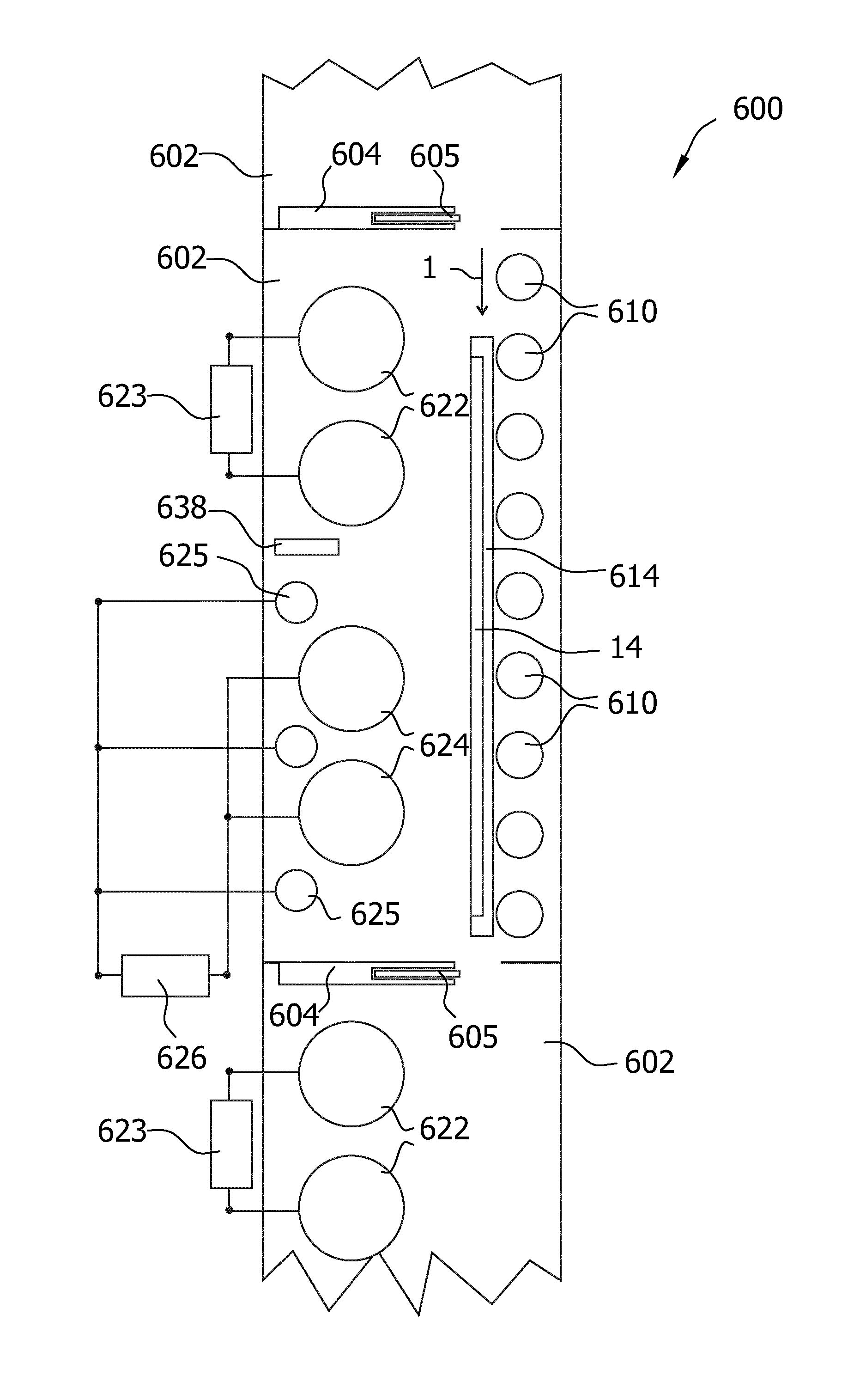
[0023]Reference will now be made in detail to the various embodiments, one or more examples of which are illustrated in the figures. Each example is provided by way of explanation, and is not meant as a limitation of the invention. It is contemplated that elements of one embodiment may be advantageously utilized in other embodiments without further recitation.

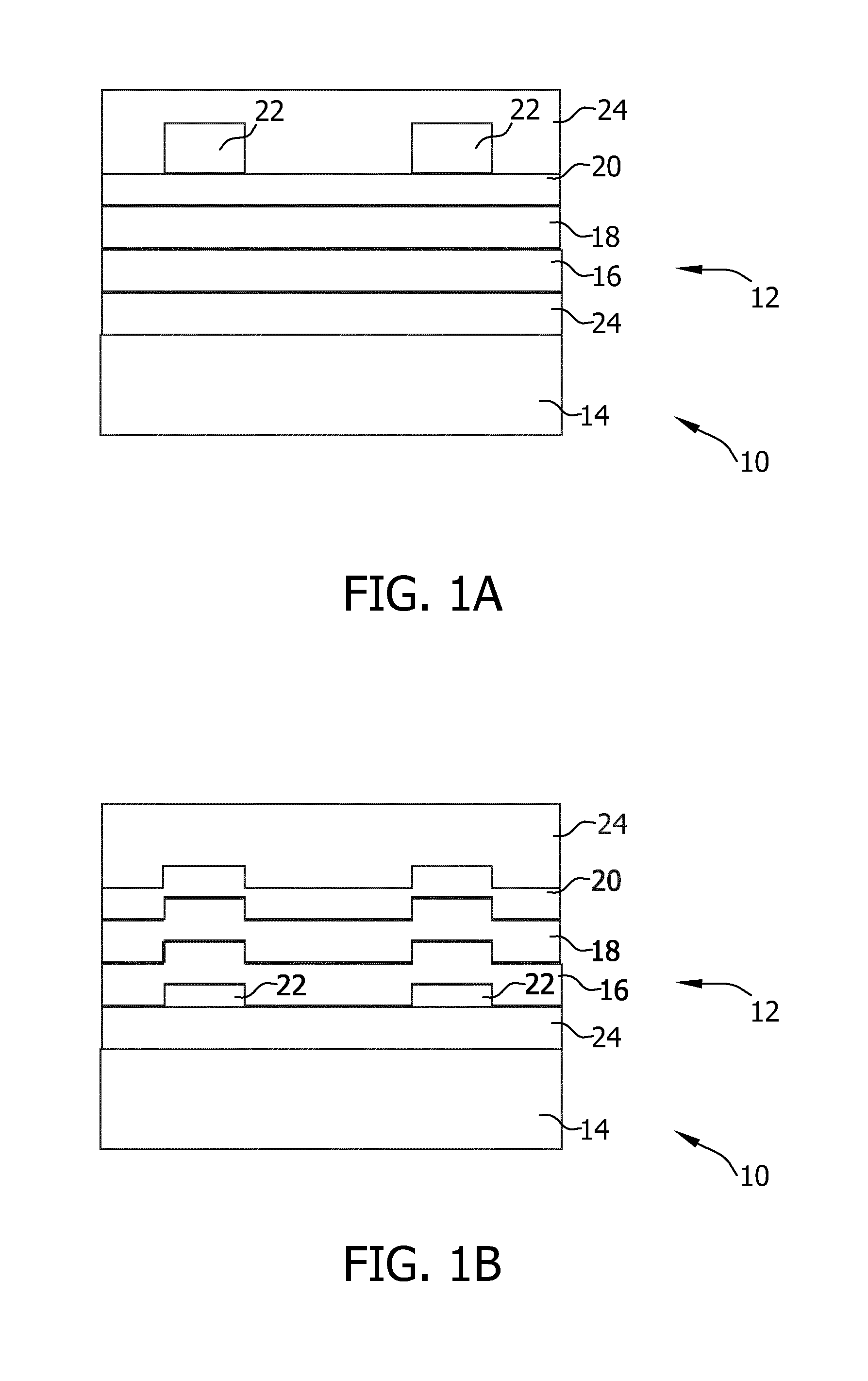
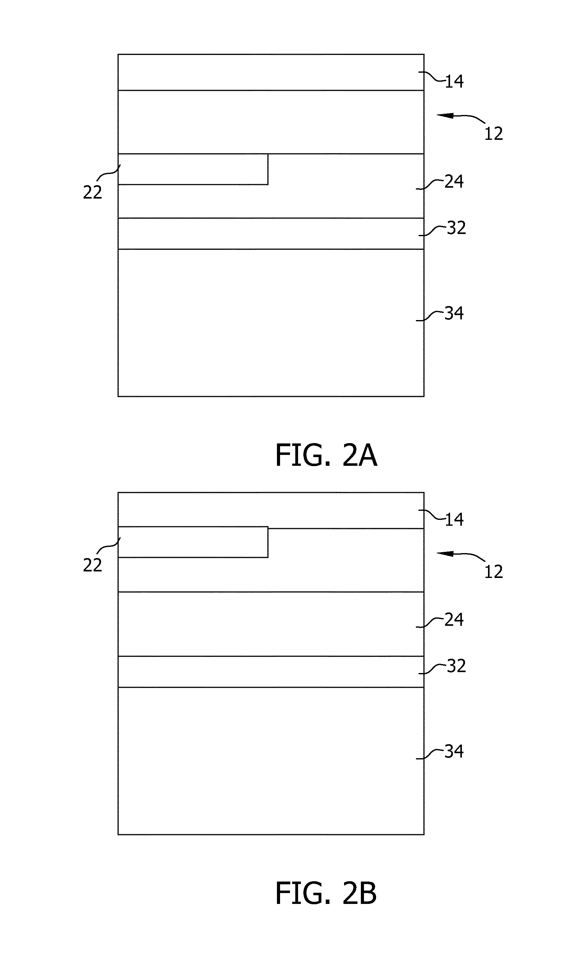
[0024]According to embodiments herein, a first transparent layer stack 12, as depicted in FIG. 1A, is deposited over a substrate 14. The term “substrate” as used herein shall embrace both inflexible substrates, e.g., a wafer, slices of transparent crystal such as sapphire or the like, or a glass plate, and flexible substrates such as a web or a foil. The term “transparent” as used herein shall particularly include the capability of a structure to transmit light with relatively low scattering, so that, for example, light transmitted therethrough can be seen in a substantially clearly manner. In the case of a flexible substrate, ...


PUM

PropertyMeasurementUnit
Thicknessaaaaaaaaaa
Sheet resistanceaaaaaaaaaa
Flexibilityaaaaaaaaaa

Abstract

A process for manufacturing a transparent body for use in a touch screen panel is provided. The process includes: depositing a first transparent layer stack over a transparent substrate, wherein said first transparent layer stack includes at least a first dielectric film with a first refractive index, and a second dielectric film with a second refractive index different from the second the first refractive index; providing a structured transparent conductive film in a manner such that the first transparent layer stack and the transparent conductive film are disposed over the substrate in this order, and wherein the structured transparent conductive film has a sheet resistance of 100 Ohm / square or below; and providing a transparent adhesive onto the structured transparent conductive film configured for attaching the layer stack to the touch screen panel.

Description

TECHNICAL FIELD[0001]Embodiments of the present disclosure relate to processes and systems for manufacturing a transparent body for use in a touch screen panel and a transparent body fabricated according to these processes.BACKGROUND ART[0002]Touch panels or touch screen panels are a particular class of electronic visual displays, which are able to detect and locate a touch within a display area. Generally, touch panels include a transparent body disposed over a screen and configured to sense a touch. Such a body is substantially transparent, so that light in the visible spectrum emitted by the screen can be transmitted therethrough. At least some known touch panels include a transparent body constituted by a barrier and a transparent conductor formed, in this order, over a substrate. A touch on the display area of such a panel generally results in a measurable change of capacitance in a region of the transparent body. The change in capacitance may be measured using different techno...

Claims


Application Information

Patent Timeline
IPC IPC(8): H05K3/00H01J37/34C23C14/35H05K1/02H05K1/03
CPCH05K3/0091H05K1/0274H05K1/0306H05K1/0313H05K2201/2054C23C14/35H01J37/3426H01J37/3405H05K2201/0108H05K1/0393G06F3/041G06F2203/04103
Inventor ZILBAUER, THOMAS WERNERGRILLMAYER, JURGEN
Owner APPLIED MATERIALS INC
Learn More