Link actuation device

a technology of actuation device and link, which is applied in the direction of programmed manipulators, instruments, and manipulators. it can solve the problems of difficult to operate the link actuation device viscerally, and increasing the size of the bearing mounting portion and/or the gear mounting portion. it can improve the driving balance of each of the actuators, shorten the stabilization time of the distal end side link hub, and improve the effect o

Active Publication Date: 2015-03-26
NTN CORP
View PDF14 Cites 35 Cited by
  • Summary
  • Abstract
  • Description
  • Claims
  • Application Information

AI Technical Summary

Benefits of technology

[0015]Another important object of the present invention is to provide a link actuation device having a large working range and a capability of accomplishing the highly accurate positioning operation at a high speed, which is compact and inexpensive, and in which, even when the parallel link mechanism is installed so as to face downwards, the lubricant falling from the parallel link mechanism and others can be prevented from falling onto the work to be processed.
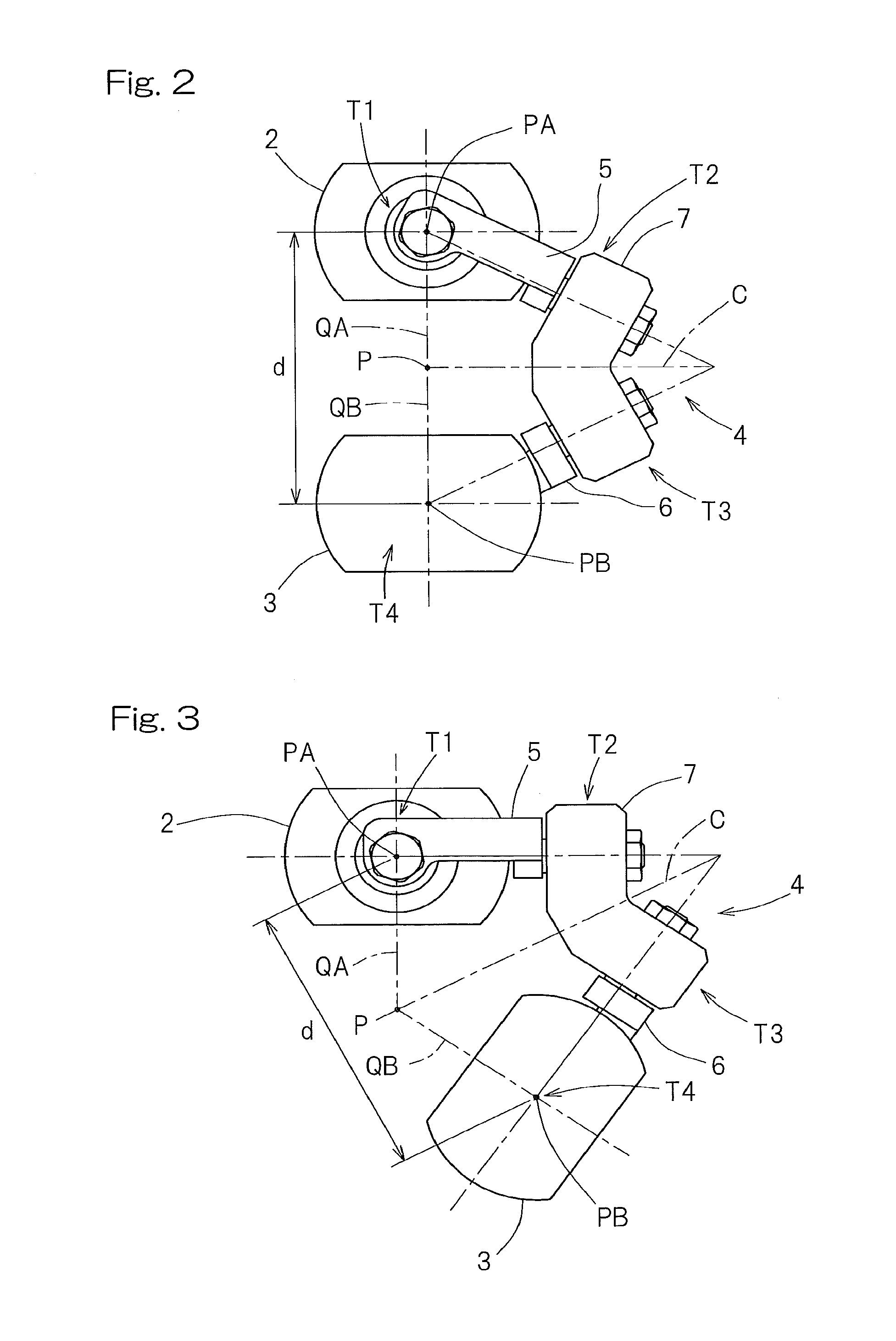
[0054]In addition, the distal end side link hub vibrates in a direction required to counterbalance the acceleration during about half the cycle of the resonant frequency. Therefore, if the deceleration time of the actuator is set to a value in the vicinity of one cycle of the resonant frequency peculiar to the link actuation device, the vibration of the distal end side link hub after a stepwise acceleration, in which the acceleration takes place cyclically, is rendered to be small particularly in the case of the stepwise acceleration. As a result thereof, the vibration of the distal end side link hub after the termination of the operation of the actuator is rendered to be small even during a high speed operation, and therefore, it is possible to allow the distal end side link hub to be operated to position at a high speed with a high accuracy.

Problems solved by technology

For this reason, the designation of the distal end orientation with the bending angle and the angle of traverse has made it difficult to operate the link actuation device viscerally.
For this reason, the operation of the link actuation device is difficult to achieve, and the skill and special training have been necessitated.
Ideally, the sealability of a bearing mounting portion and / or a gear mounting portion has to be increased to avoid the possibility that the lubricant may leak from the bearing and / or the gears, but this leads to the increase in size of the bearing mounting portion and / or the gear mounting portion, which in turn leads to the increase in size of the mechanism as a whole and to the cost increase.
Also, although it may be contemplated to install a covering to cover the parallel link mechanism in its entirety, it has been difficult to install such a covering without interfering the operation of the parallel link mechanism.
Also, since the link actuation device disclosed in the above mentioned patent document 2 is such that the position and the orientation of the distal end side member relative to the proximal end side member are changed through a link mechanism, particularly where the position and orientation of the distal end side member are changed at a high speed, the problem has arisen that the stabilization time, which is the length of time required to complete the positioning of the distal end side member, tends to be increased due to the rigidity of the link mechanism.

Method used


Image

  • Link actuation device
  • Link actuation device
  • Link actuation device

Examples


second embodiment

[0147]The gear type decelerating unit 73A includes a small gear 76, which is connected with an output shaft 70b of the actuator 70 through a coupling 75 in a rotation transmittable fashion, and a large gear 77 fixed to the proximal side end link member 5 and meshed with the small gear 76. In the second embodiment, each of the small gear 76 and the large gear 77 is in the form of a spur gear, and the large gear 77 is a sector shaped gear having teeth formed in a peripheral surface of the sector shape. The large gear 77 has the pitch circle radius that is greater than that of the small gear 76, and the rotation of the output shaft 70b of the actuator 70 is reduced to a rotational axis O1 of the revolve pairing portion T1 between the proximal end side link hub 2 and the proximal side end link member 5 and then transmitted to the proximal side end link member 5. The gear ratio thereof is rendered to be larger than 10.

[0148]The pitch circle radius of the large gear 77 is equal to or grea...

sixth embodiment

[0167]According to the above described construction in accordance with the sixth embodiment, since a portion on one side of the fixing member 205 in the parallel link member 1 adjacent the distal end side is extensively covered by the lubricant recovery member 200, the lubricant then scattered from the parallel link mechanism 1 and the decelerating unit 73 during the operation can be received by the lubricant recovery member 200. Since the projection 206 is provided in an outer peripheral end on the fixing member 205, even though the lubricant falls onto the fixing member 205, such lubricant will not fall outside the fixing member 205 and, therefore, the possibility of the work to be processed being wetted with the lubricant can be avoided. Since the connecting portion 208 is stretchable, even though the orientation of the distal end side link hub 3 relative to the proximal end side link hub 2 changes, the connecting portion 208 of the lubricant recovery member 200 can deform in res...

eighth embodiment

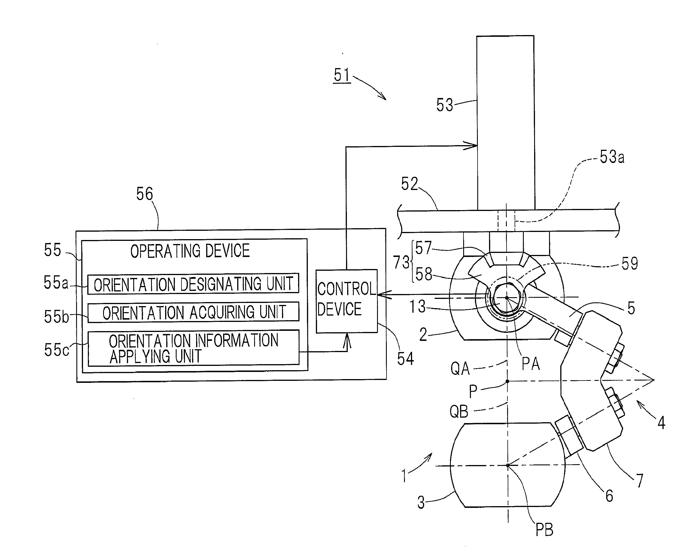
[0169]FIG. 19 illustrates the eighth preferred embodiment of the present invention. The link actuation device 51 of the eighth embodiment includes a lubricant recovery member 210 for receiving the lubricant falling downwardly from the bevel gears 57 and 58 of the decelerating unit 73. The lubricant recovery member 210 is of a dish-like member having a plate shaped portion 211, positioned immediately below the decelerating unit 73, and a projecting portion 212 protruding from an outer peripheral edge of the plate shaped portion 211 towards the base member 52. The lubricant recovery member 210 is fitted to the base member 52 by means of a bolt (not shown) through a mounting portion 213 linked with a portion of the projecting portion 212. This lubricant recovery member 210 is prepared from, for example, sheet metal.

[0170]The use of the lubricant recovery member 210 of such a structure as hereinabove described is effective to avoid the possibility that the lubricant falling from the dec...


PUM


Abstract

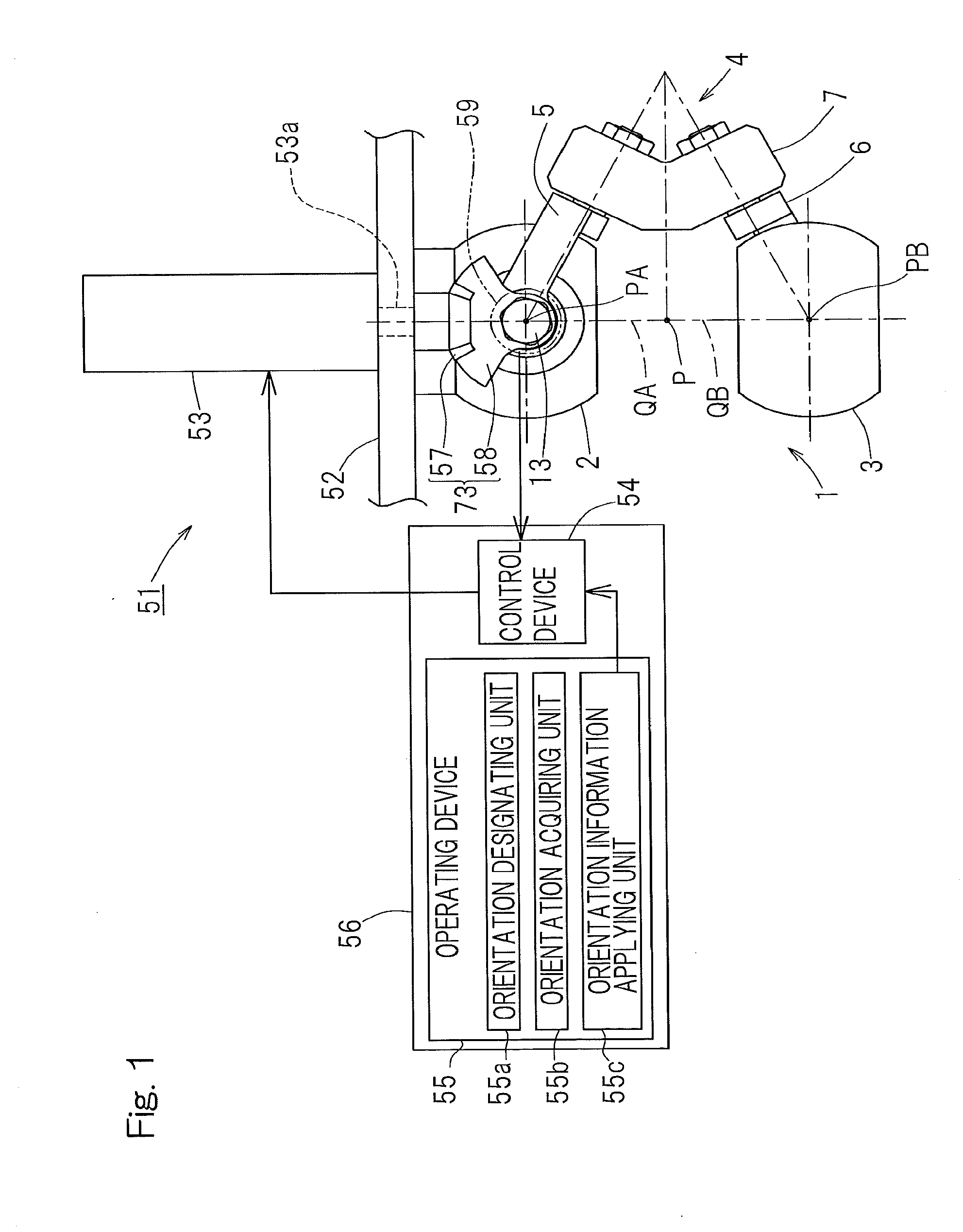
A link actuation device includes a distal end side link hub connected with a proximal end side link hub through three or more sets of link mechanisms for alteration in orientation. By means of an actuator provided in the two or more set of the link mechanism, the distal end orientation, which is the orientation of the distal end side link hub relative to the proximal end link hub, is changed arbitrarily. The operating device includes an orientation designating unit for designating the distal end orientation aimed at by means of a coordinate position on the orthogonal coordinate system by an artificial manipulation, an orientation acquiring unit for acquiring the distal end orientation that is expressed by an angular coordinate system through calculation, and an orientation information applying unit for applying information on the distal end orientation so acquired to a control device for controlling the actuator.

Description

CROSS REFERENCE TO THE RELATED APPLICATION[0001]This application is based on and claims Convention priority to Japanese patent applications No. 2012-066888, filed Mar. 23, 2012, No. 2012-073373, filed Mar. 28, 2012, and No. 2012-144106, filed Jun. 27, 2012, the entire disclosures of which are herein incorporated by reference as a part of this application.BACKGROUND OF THE INVENTION[0002]1. Field of the Invention[0003]The present invention relates to a link actuation device used in, for example, a parallel link mechanism or a robot articular mechanism which speedily and precisely execute a work such as, for example, a complicate processing or handling of articles in a three dimensional space and, more particularly, to a link actuation device, an operating device therefor, a method of controlling it and a control device therefor, all of which require a precise and extensive operating range of, for example, medical instruments and industrial equipments.[0004]2. Description of Related A...

Claims


Application Information

Patent Timeline
Patent Type & Authority Applications(United States)
IPC IPC(8): B25J9/00B25J9/12B25J9/16
CPCB25J9/0048B25J9/12B25J9/1623B25J13/087G05B2219/39476G05B2219/40555
Inventor ISOBE, HIROSHINISHIO, YUKIHIROYAMADA, HIROYUKI
Owner NTN CORP
Why Eureka
Try Eureka