Multi-stage SCR Control and Diagnostic System

Active Publication Date: 2015-04-09
QI BAOHUA
View PDF1 Cites 84 Cited by
  • Summary
  • Abstract
  • Description
  • Claims
  • Application Information

AI Technical Summary

Benefits of technology

[0016]In controlling the reductant dosing rates, target deNOx efficiencies are used for determining reductant dosing commands for the front and the back reductant injecting devices. The goal of the controls is to keep the deNOx efficiencies of the front and the back SCR devices at the target deNOx efficiency values, and feedback controls can be used for further improving the

Problems solved by technology

In lean combustion engines, due to the existence of large amount oxygen excess, passive means without extra dosing agents, such as that using a three-way catalyst, normally are not able to effectively remove the oxidative specie NOx, as that in most of spark-ignition engines.
However, due to safety concerns and difficulties in handling pure ammonia, in ammonia SCR systems, normally ammonia is obtained from a urea solution through thermolysis and hydrolysis, and the urea solution in these applications is also called reductant.
In a SCR system, dosing accuracy significantly affects NOx control performance, especially when engine out NOx level is high.
Though in transient, SCR catalyst has certain capability storing ammonia, damping the effects of under-dosing and over-dosing, in average, these effects may still cause issues.
Other important factors, such as NOx sensor error, urea decomposition error, and exhaust flow rate error, also could contribute to the overall control uncertainty.
However, relying on the storage capability of SCR catalyst and AMOX could cause aging issues, since both of the storage capability of SCR catalyst and the selectivity of AMOX are subject to aging effects.
An aged AMOX tends to oxidize ammonia slip back to NOx, and an aged SCR catalyst has lower deNOx efficiency.
Therefore, the aging of the catalysts may cause NOx slips with over-dosing, especially when temperature variation releases stored ammonia in SCR catalyst.
Additionally at high NSRs, deNOx efficiency is more sensitive to catalyst aging than at low NSRs, and the high sensitivity to

Method used


Image

  • Multi-stage SCR Control and Diagnostic System
  • Multi-stage SCR Control and Diagnostic System
  • Multi-stage SCR Control and Diagnostic System

Examples


Embodiment Construction

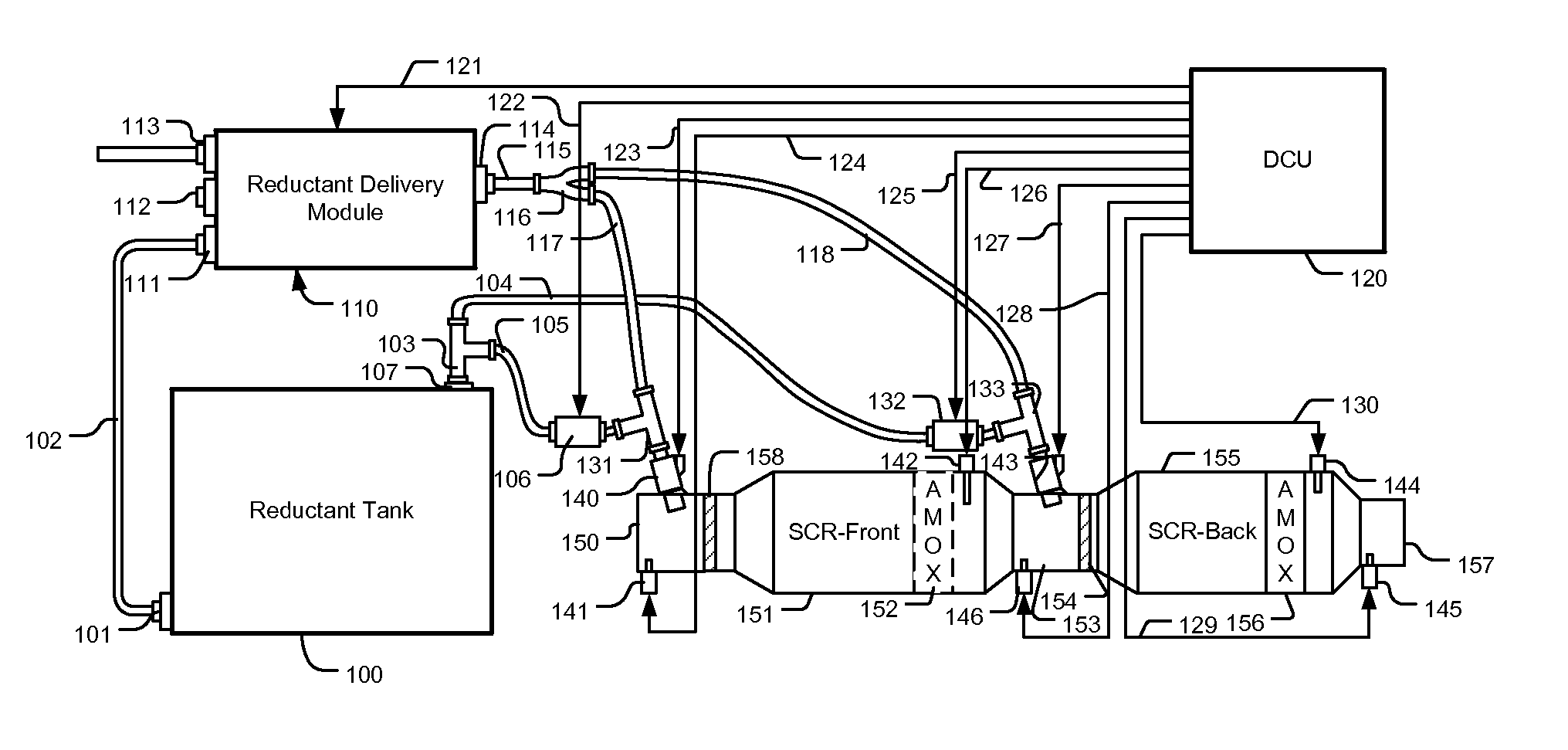
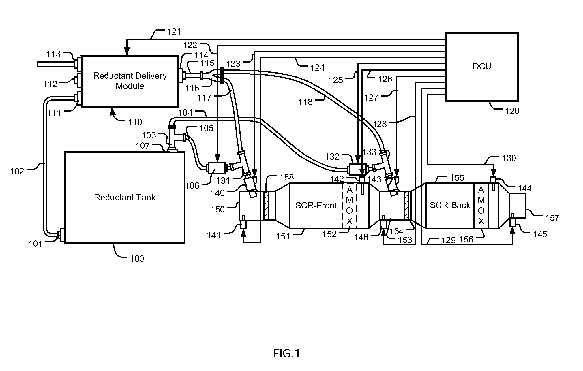
[0034]Referring to FIG. 1, a two-stage SCR system includes two SCR devices, a front SCR device and a back SCR device. The front SCR device has a SCR catalyst 151 and an optional AMOX 152 inside, and the catalyst 151 is at the front of the AMOX 152. Upstream from the front SCR device, an injector 140, which is controlled by a DCU 120 through signal lines 123, is installed on an exhaust gas passage 150 for delivering reductant into exhaust flow, and a temperature sensor 141 is positioned upstream from the injector 140 for providing temperature sensing signals to the DCU 120 through signal lines 124. In between the injector 140 and the catalyst 151, in the exhaust gas passage 150, a mixer 158 is used for creating a uniform exhaust flow. Downstream from the AMOX 152, a NOx sensor 143 electrically connected to the DCU 120 through signal lines 126 is used for measuring NOx concentration in exhaust gas, and an exhaust gas passage 153 connects the front SCR device to the back SCR device, in...


PUM


Abstract

A multi-stage SCR control system including a front reductant dosing device, a front SCR device, a back reductant dosing device, a back SCR device, and a dosing controller. In normal control cycles, a NSR of the front SCR device is controlled below a stoichiometric reaction ratio to decrease system sensitivity to catalyst aging. In a diagnostic cycle, the NSR of the front or the back SCR device is controlled lower than the stoichiometric reaction ratio, and a reductant quality ratio, which is indicative of reductant quality and dosing accuracy, is calculated. In another diagnostic cycle, the NSR is controlled above the stoichiometric reaction ratio, and an average deNOx efficiency is calculated. The reductant quality ratio and the average deNOx efficiency values are further used in SCR feedback control and permanent catalyst damages can also be isolated from temporary catalyst poisons with these values after a thermal recovery event is completed.

Description

[0001]This present application claims priority from U.S. provisional application No. 61 / 886,243 having the same title as the present invention and filed on Oct. 3, 2013.[0002]The present invention relates to an exhaust system for an internal combustion engine, and more specifically, to an exhaust system with a SCR (Selective Catalytic Reduction) apparatus for reducing NOx (Nitrogen Oxides) in exhaust gas of an internal combustion engine.BACKGROUND OF THE INVENTION[0003]Environmentally harmful species in exhaust gas emitted from an internal combustion engine, such as hydrocarbons (HC), carbon monoxide (CO), particulate matters (PM), and nitric oxides (NOx) are regulated species need to be removed therefrom. In lean combustion engines, due to the existence of large amount oxygen excess, passive means without extra dosing agents, such as that using a three-way catalyst, normally are not able to effectively remove the oxidative specie NOx, as that in most of spark-ignition engines. To r...

Claims


Application Information

Patent Timeline
IPC IPC(8): F01N3/20
CPCF01N3/206F01N2610/00F01N2570/14F01N3/208F01N9/00F01N13/0093F01N2610/02F01N2610/14F01N2610/146F01N2900/0408F01N2900/1621F01N2900/1818Y02T10/12Y02T10/40
Inventor QI, BAOHUA
Owner QI BAOHUA
Why Eureka
Try Eureka