
Bidirectional dc-dc converter

a dc-dc converter and bi-directional technology, applied in the direction of electric variable regulation, process and machine control, instruments, etc., can solve the problems of low step-up and step-down voltage conversion ratio, complicated circuit configuration, and complicated control circuit, so as to reduce increase the conversion ratio of boost or buck, and reduce the switching loss and conduction loss

Inactive Publication Date: 2015-04-09
NATIONAL TSING HUA UNIVERSITY
View PDF3 Cites 52 Cited by
  • Summary
  • Abstract
  • Description
  • Claims
  • Application Information

AI Technical Summary

Benefits of technology

This patent presents a new type of DC-DC converter that has low stress on switches, which makes it suitable for use in low-voltage energy systems. It has two main modes of operation: boost and buck. When in boost mode, it combines with a two-phase boost converter to provide a high step-up voltage gain, without requiring a high duty ratio. In buck mode, it combines with a two-phase buck converter to get a high step-down conversion ratio, without requiring a short duty ratio. The converter uses capacitors to store energy and increase the conversion ratio, while reducing the stress on the switches. This results in improved efficiency and the use of lower-rated MOSFETs. The converter also has an automatic current sharing characteristic, without needing extra circuitry or complex control methods. Overall, this new converter design has better performance and is more efficient for energy resource applications.

Problems solved by technology

This control circuit becomes more complicated.
However, the step-up and step-down voltage conversion ratios are low.
However, their circuit configurations are complicated.
However, the step-up and step-down voltage conversion ratios also are low.

Method used


Image

  • Bidirectional dc-dc converter
  • Bidirectional dc-dc converter
  • Bidirectional dc-dc converter

Examples


Embodiment Construction

[0019]The following content combines with the drawings and the embodiment for describing the present invention in detail.

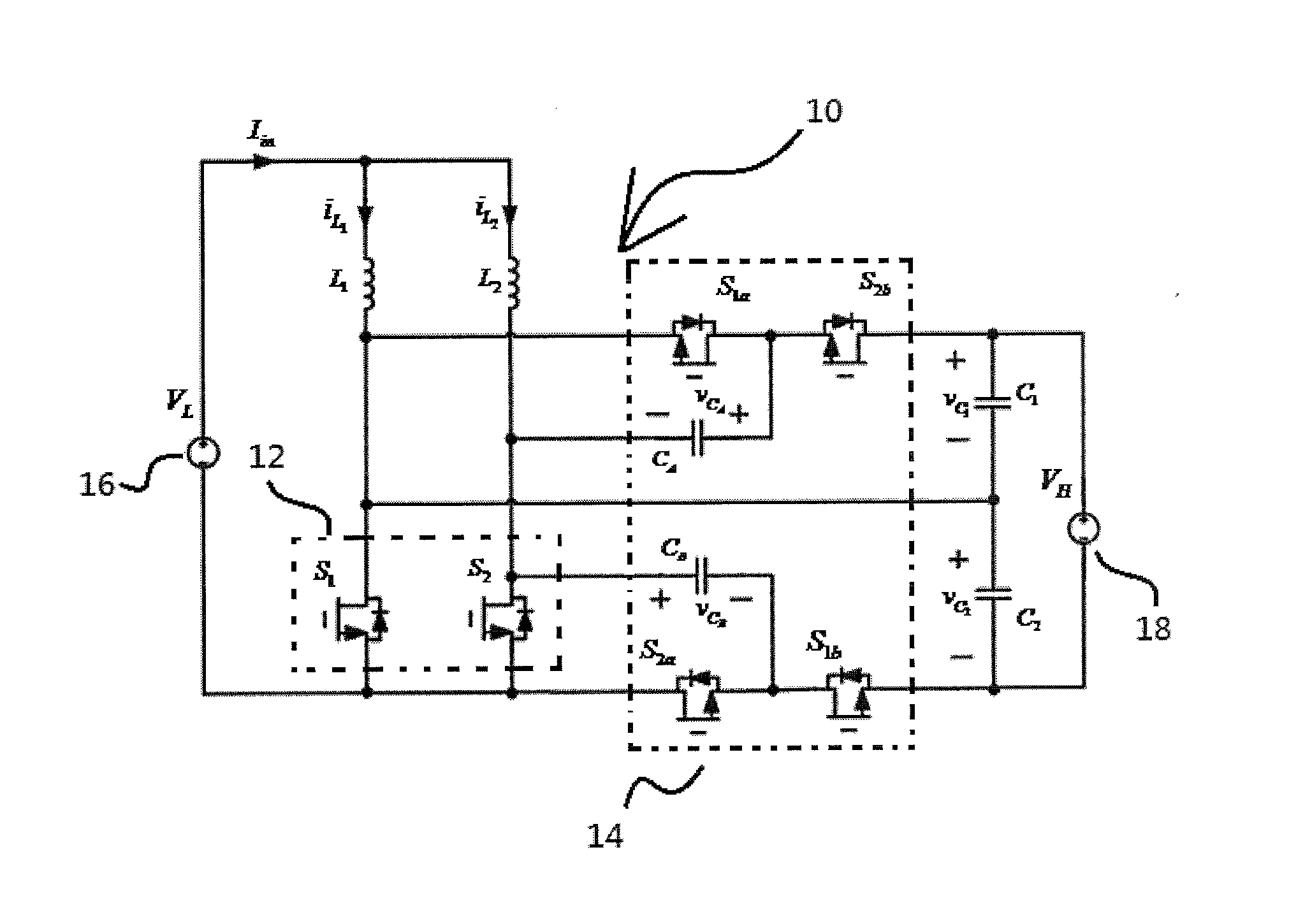
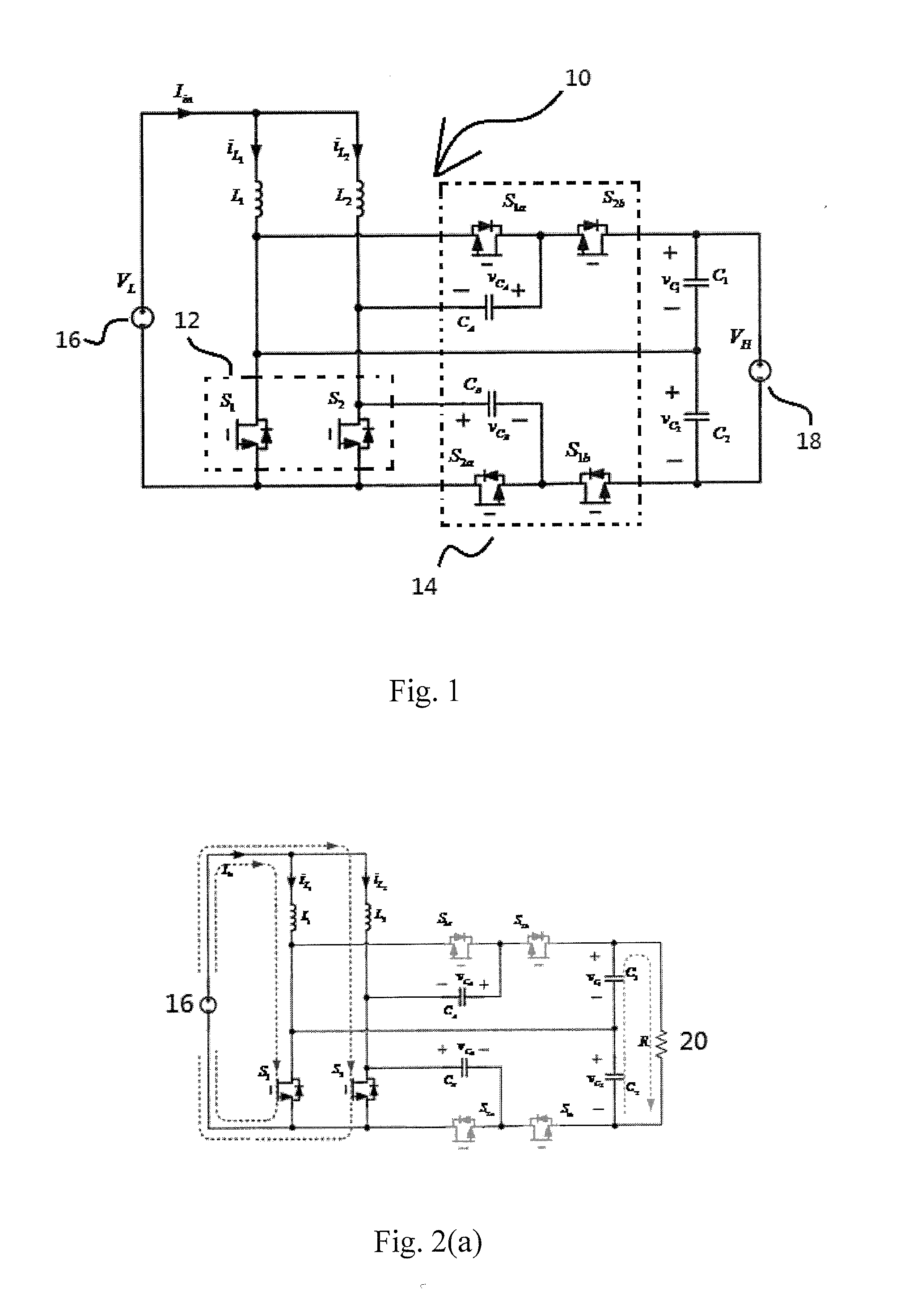
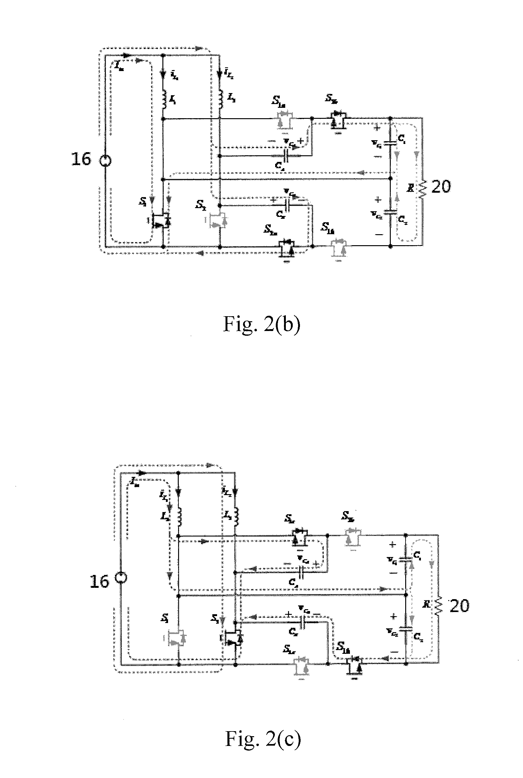
[0020]With reference to FIG. 1, the DC-DC converter 10 is comprised of a switch set 12 which have a first switch S1 and a second switch S2, an operating switch set 14 which have four operating switches, a first operating switch S1a, a second operating switch S1b, a third operating switch S2a, and a fourth operating switch S2b, two blocking capacitors CA and CB, two inductors L1 and L2 and two capacitors C1 and C2. Wherein, one end of the inductors L1 and L2 is connected to a first voltage source 16, and the other end of the inductors L1 and L2 is connected to the first switch S1 and the second switch S2 respectively. Two capacitors C1 and C2 are connected in series and the other end of the capacitors C1 and C2 is connected to second voltage source 18 in parallel. In order to simplify the circuit analysis of the invention converter, some assumptions are made as fol...


PUM


Abstract

A bidirectional converter circuit includes a voltage source which provides an input voltage, an energy storage set connected to the voltage source and receives the input voltage, a switch set connected to the energy storage set, wherein the switch set includes a first switch and a second switch; an operating switch set connected to the switch set, wherein the operating switch set includes a first operating switch, a second operating switch, a third operating switch and a fourth operating switch. The bidirectional converter further includes a blocking capacitor set and a (input / output) capacitor set. Wherein, the blocking capacitor set is connected to the switch set and the operating switch set. The first operating switch and the second operating switch are driven complementarily with the first switch, and the third operating switch and the fourth operating switch are driven complementarily with the second switch.

Description

BACKGROUND OF THE INVENTION[0001]1. Field of the Inventions[0002]The present invention relates to a non-isolated bidirectional DC / DC converter with high conversion ratio and low switch voltage stress characteristic, in particularly, to a novel transformer-less two-phase interleaved bidirectional DC / DC converter with high efficiency.[0003]2. Description of Related Art[0004]Recently bidirectional dc-dc converters (BDC) have received a lot of attention due to the increasing need to systems with the capability of bidirectional energy transfer between two dc buses. Apart from traditional application in dc motor drives, new applications of BDC include energy storage in renewable energy systems, fuel cell energy systems, hybrid electric vehicles (REV), uninterruptible power supplies (UPS), PV hybrid power systems and battery chargers.[0005]Various BDCs can be divided into the non-isolated BDCs and isolated BDCs. Non-isolated BDCs (NBDC)are simpler than isolated BDCs (IBDC) and can achieve ...

Claims


Application Information

Patent Timeline
IPC IPC(8): H02M3/158
CPCH02M3/158H02M3/1584Y02B70/10H02M1/0054H02M3/1586
Inventor PAN, CHING-TSAICHUANG, CHEN-FENG
Owner NATIONAL TSING HUA UNIVERSITY
Learn More