Methods and devices for repair of vaginal wall or uterus

a vaginal wall and uterus technology, applied in the field of vaginal wall or uterus surgical repair, can solve the problems of high failure rate of vaginal repair approach, intraoperative hemorrhage, postoperative stress incontinence, etc., and achieve the effect of stabilizing the placement of the reinforcing implant and facilitating the placement of the vaginal apex

Inactive Publication Date: 2015-04-09
GYNAECOLOGIC
View PDF3 Cites 9 Cited by
  • Summary
  • Abstract
  • Description
  • Claims
  • Application Information

AI Technical Summary

Benefits of technology

[0044]Preferably, there is substantially tensionless placement of the reinforcing implant prior to tissue in-growth. That is, the reinforcing implant is not in tension immediately following its positioning. It is desirable to avoid use of sutures, anchors, clips, staples or other fasteners to maintain the position of the tongue of the reinforcing implant anterior to or in contact with the sacrum. Instead, it is desirable to stabilize placement of the reinforcing implant using the vaginal splinting appliance which remains in the vaginal canal for a duration sufficient to achieve tissue in-growth into the reinforcing implant. In one embodiment, ideal placement is with the tongue of the reinforcing implant resting along the anterior curvature of the sacral hollow and/or sacral promontory. A biocompatible resorbable adhesive may be used to assist with and/or stabilize placement prior to tissue in-growth.
[0045]In one embodiment, the method includes, prior to attaching the body of reinforcing implant to the vaginal wall, elevating the vaginal vault to facilitate location of the v...

Problems solved by technology

Pelvic organ prolapse and vaginal vault prolapse occurs after failure of these direct and indirect supporting mechanisms and is frequently accompanied by weakness of the muscular pelvic floor and suspensory fibers of the parametrium and upper paracolpium.
This vaginal repair approach has a high failure rate with around 30% of women surgically treated for prolapse requiring repeat surgery for recurrent pelvic floor symptom.
Significant problems associated with the ASC operation include de novo postoperative ...

Method used


Image

  • Methods and devices for repair of vaginal wall or uterus
  • Methods and devices for repair of vaginal wall or uterus
  • Methods and devices for repair of vaginal wall or uterus

Examples


Embodiment Construction

[0068]The present invention provides improvements in a vaginal splinting appliance, elevator device and method for repair of a vaginal wall or uterus as described in

[0069]International patent application PCT / AU2011 / 001385 filed 28 Oct. 2011, the entire contents of which are hereby incorporated herein by reference.

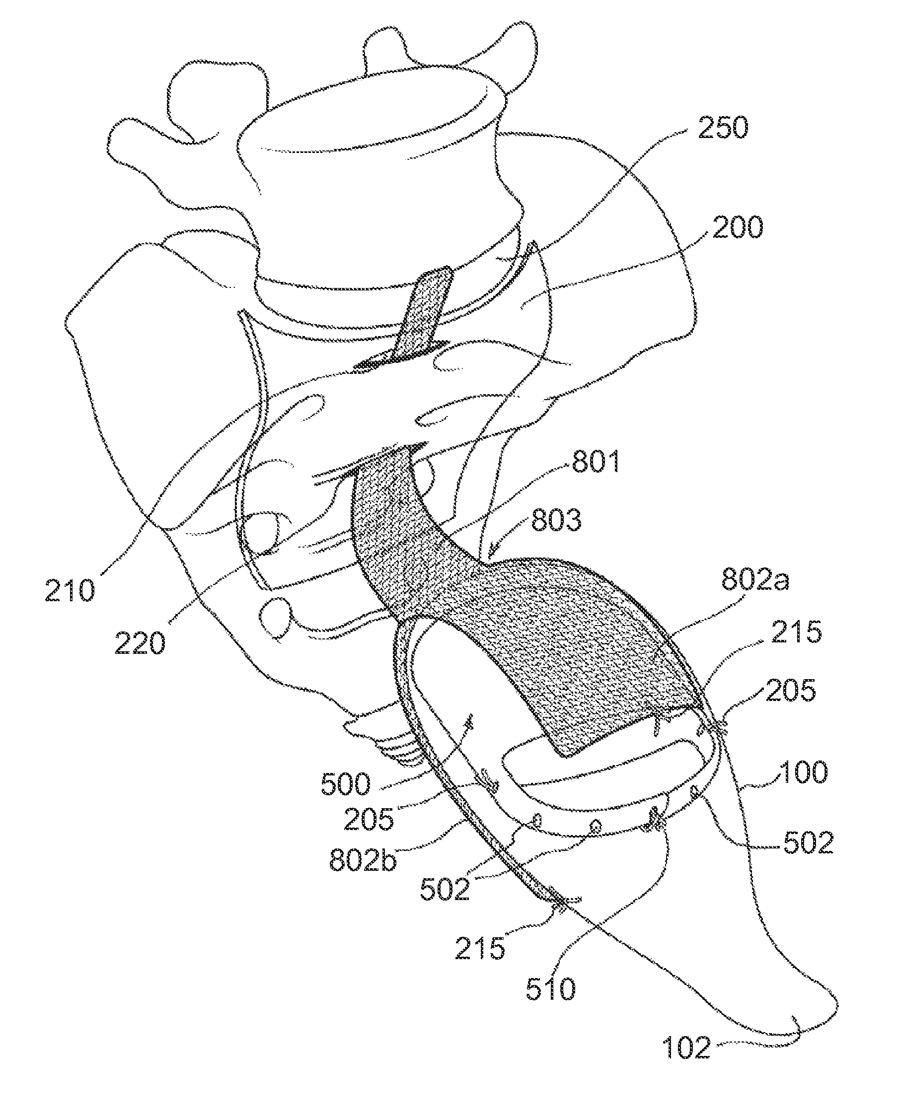
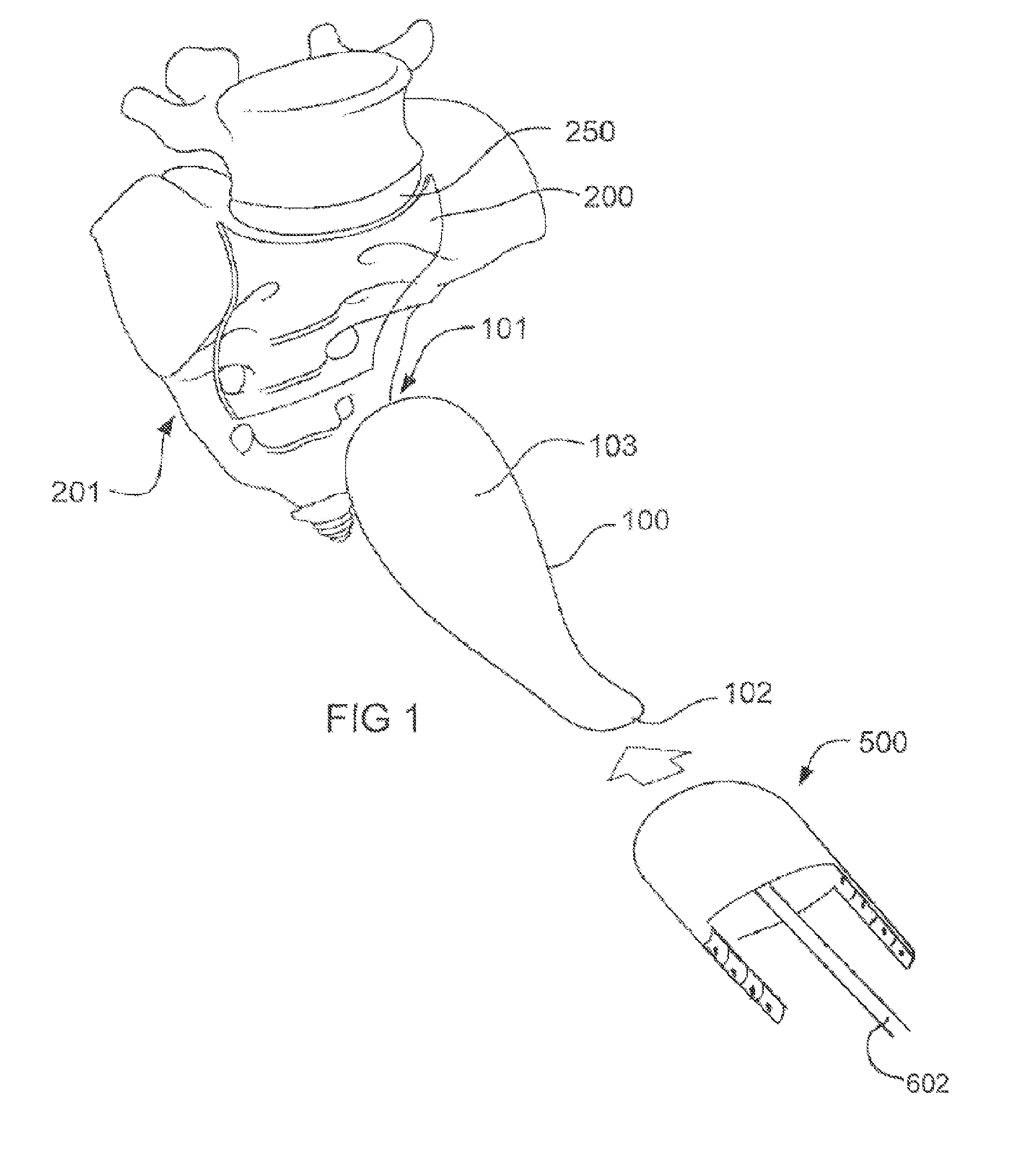
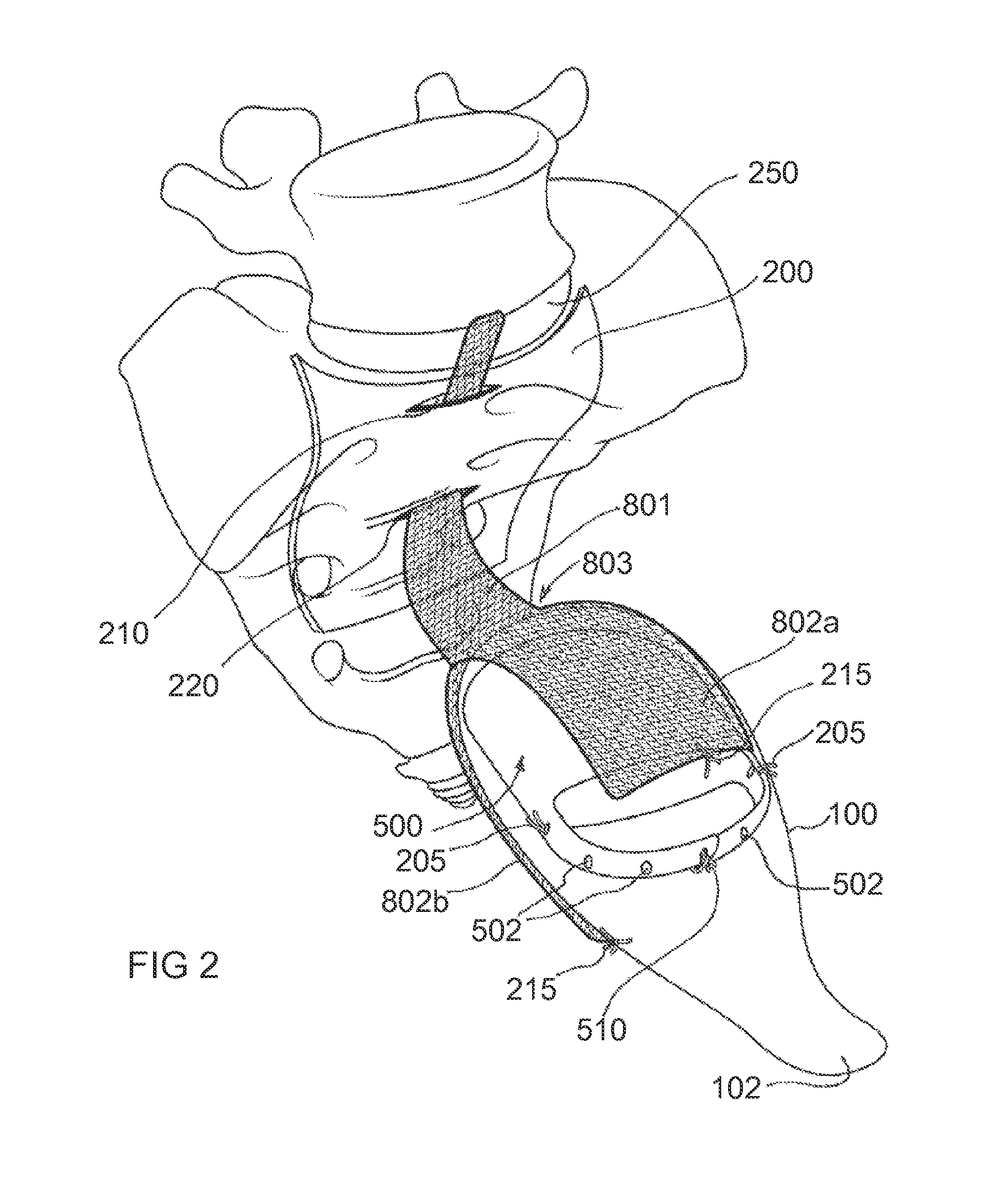
[0070]Referring firstly to FIG. 1, components of the pelvic anatomy of a woman are shown in a schematic illustration. Vaginal canal 100 has apex 101 and opening 102 into which vaginal splinting appliance 500 is inserted. Prior to insertion, the vaginal splinting appliance is coupled with the body 601 of a vaginal elevator device 600 (see FIGS. 4a, 4b) of which only shaft 602 is visible in FIG. 1. A portion of the sacral peritoneum 200 is shown, overlaying part of the sacrum 201 in the region of the sacral curve.

[0071]Following induction with general anesthesia the woman is placed in a low lithotomy position. Preferably the inventive surgical method is performed via laparosc...


PUM

PropertyMeasurementUnit
Lengthaaaaaaaaaa
Lengthaaaaaaaaaa
Lengthaaaaaaaaaa

Abstract

A splinting appliance for use in repair of the vaginal wall or uterus includes a body portion, securing means and coupling means. The body portion is shaped to support a substantially normal vaginal apex. The securing means is configured to enable removable securing of the splinting appliance within the vaginal canal. The coupling means enables the splinting appliance to releasably couple with a vaginal elevator device when inserted in the vaginal canal during surgery. Use of the vaginal elevator device when coupled with the splinting appliance aids in location of the vaginal apex. The splinting appliance provides a substantially rigid support which, when in use, facilitates manipulation of tissue at the vaginal wall when approaching through the abdomen e.g. for dissection and/or attachment of a repair graft.

Description

FIELD OF THE INVENTION[0001]This invention relates to a method for surgical repair of a vaginal wall or uterus due to pelvic organ prolapse. It relates particularly but not exclusively to a method performed by laparoscopy or other minimally invasive technique which provides abdominal access to the vaginal wall, and a splinting apparatus for use during the surgery and during initial convalescence of the woman undergoing treatment and elevator device for use during surgery.BACKGROUND TO THE INVENTION[0002]Vaginal prolapse is a condition in which the bladder, uterus and / or bowel protrude into the vagina, typically due to loss of natural support for the pelvic organs and the vaginal vault in women who have undergone a prior hysterectomy. In the normal female anatomy, direct support for the vaginal vault is provided by the parametrium (cardinal and uterosacral ligaments) and paracolpium fibers. These fibers act like suspensory ligaments and arise from the fascia of the piriformis muscle,...

Claims


Application Information

Patent Timeline
IPC IPC(8): A61F6/12A61F2/00
CPCA61F6/12A61F2/0063A61F2002/0072A61F2250/0059A61F2250/006A61F2220/0033A61F2220/0016A61B17/42A61B17/4241A61F2/0045A61F2210/0004A61F2230/006A61F2250/0071
Inventor CAREY, MARCUS PATRICK
Owner GYNAECOLOGIC
Why Eureka
Try Eureka