

High pressure fluid system
a fluid system and high-pressure technology, applied in the direction of valve housings, liquid fuel engines, machines/engines, etc., can solve the problems of high wear and tear of components of such assemblies or systems, high operating stress and wear of components, and difficult access, so as to reduce manufacturing, assemble and service the effect of less components and fewer components
- Summary
- Abstract
- Description
- Claims
- Application Information
AI Technical Summary
Benefits of technology
Problems solved by technology
Method used
Image

Examples
first alternative embodiment
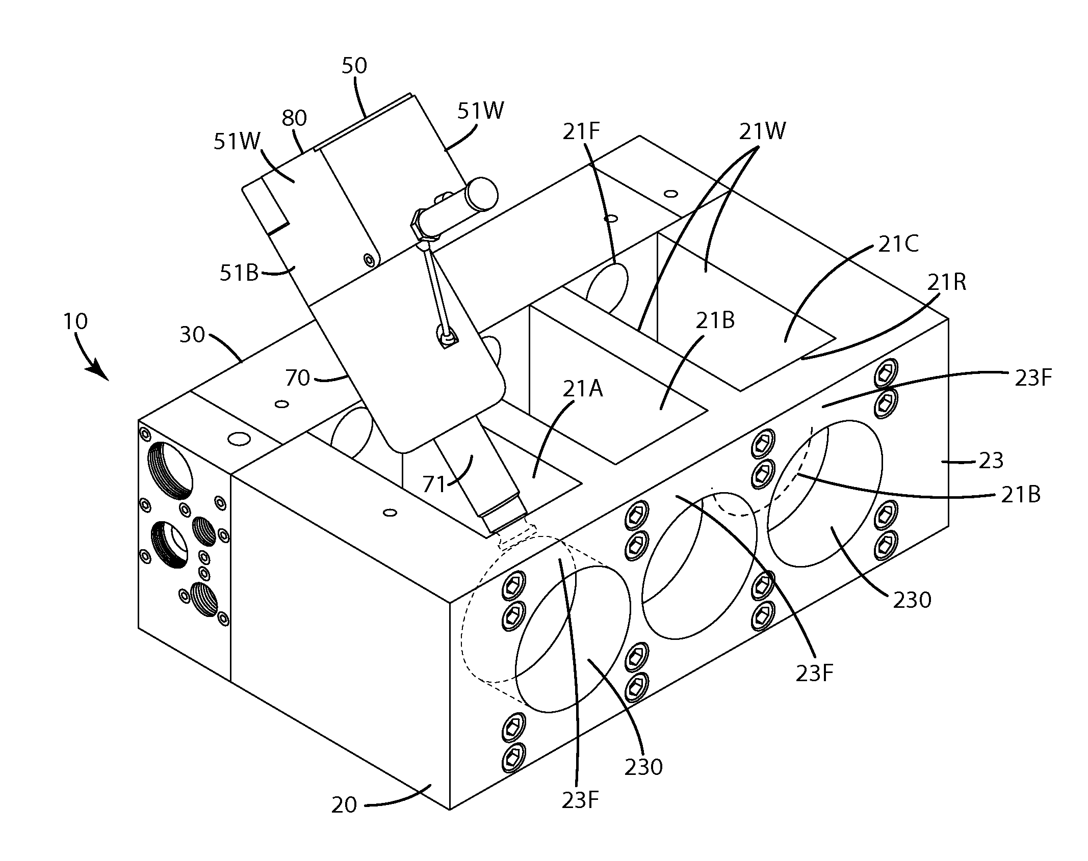
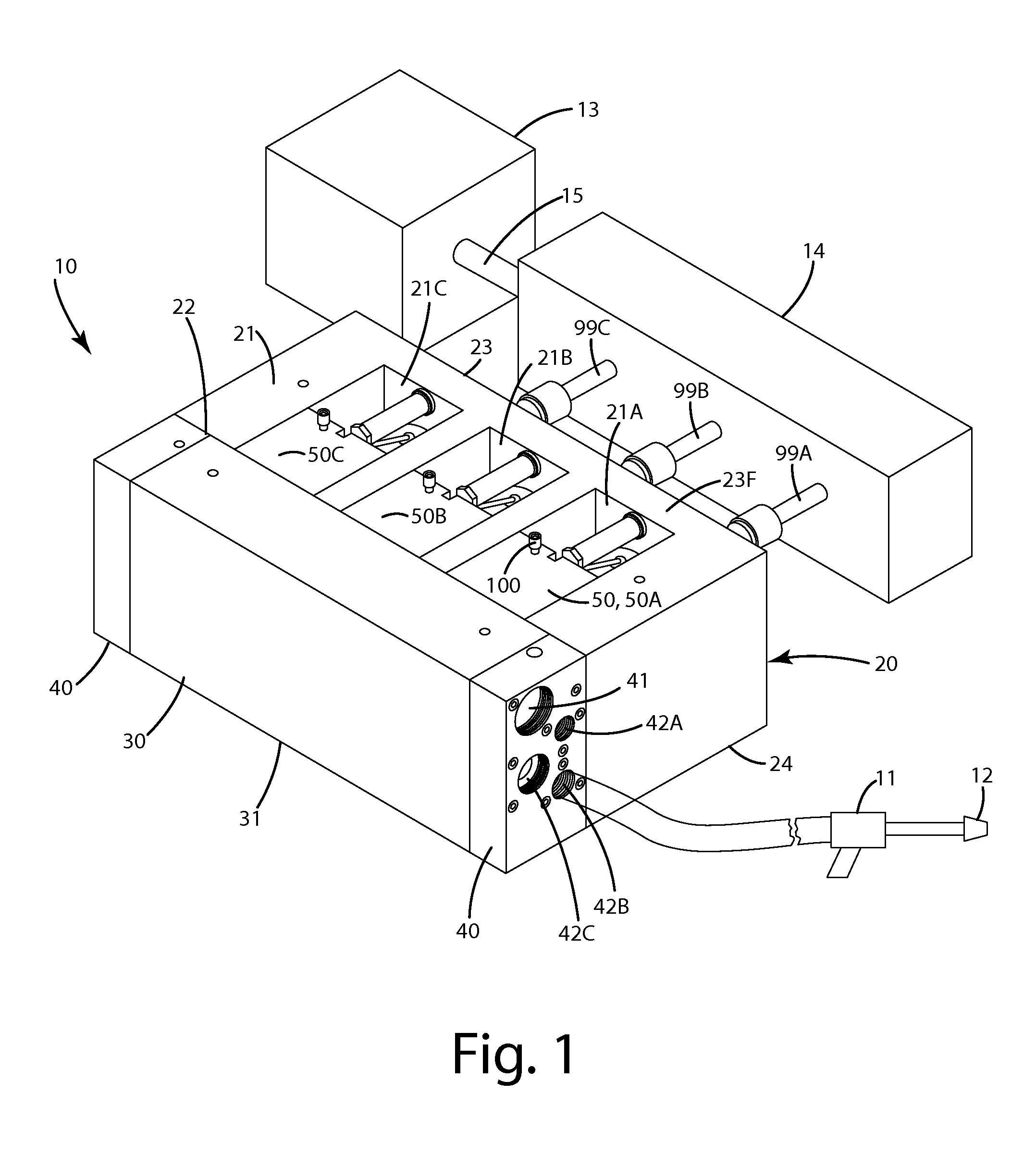
[0159]A first alternative embodiment of the high pressure fluid end system with its components is shown in FIGS. 27-41 and generally designated 110. This fluid end is similar and / or identical in structure, function and components to the embodiment described above with several exceptions. For example, the fluid end system 110 includes a frame 120 to which a discharge manifold 130 is joined or monolithically formed therewith. The discharge manifold alternatively can be bolted on with a series of bolts able to withstand the extreme pressures at which the fluid end system operates.
[0160]Like the embodiment above, the fluid end system can 110 be configured for attachment to a drive unit via a transmission and multiple cross head stubs (not shown). The fluid end system 110 also is configured for attachment to blasting equipment 10, for example, a spray gun having a nozzle 12 for shooting liquid at high pressures as shown in FIG. 29. This blasting equipment, as mentioned in the embodiment ...
PUM
 Abstract
Description
Claims
Application Information