Eureka AIR delivers breakthrough ideas for toughest innovation challenges, trusted by R&D personnel around the world.

Light weight cable

Inactive Publication Date: 2015-04-23
OLEX AUSTRALIA +1
View PDF14 Cites 2 Cited by
  • Summary
  • Abstract
  • Description
  • Claims
  • Application Information

AI Technical Summary

Benefits of technology

The invention is a high strength, light weight cable designed for use in electrical power distribution systems. It includes a central core, a conductive layer on the core, and an outer insulation layer. The core can be made of a composite of matrix material and light weight strength fibers. The matrix material can be epoxy, and the fibers can be carbon fibers or ceramic fibers. The conductive layer can be made of aluminum, copper, or alloy of aluminum. The outer insulation layer can be made of high density polyethylene or cross-linked polymer. The cable has a thin exterior and can be installed on existing poles. Its high strength to weight ratio makes it ideal for use in power distribution systems.

Problems solved by technology

Such systems are difficult to adequately protect due to the high “impedance / resistance” of the circuit and earthing arrangements.
If the line breaks and falls to the ground or if a tree should touch the line then sparks may occur before the circuit protection systems operate.
This can start bush fires and with the risk of loss of life and property damage.
Putting the supply underground would solve the problem but this is too expensive in most cases particularly as the voltage to earth is either 12.7 kV or 19 kV.
Using conventional HV aerial bundled cable (ABC) would also be too costly and require more poles.
However this cannot in many cases be done with conventional materials and conductor designs using Aluminium Clad Steel wires or composite steel and aluminium because the added weight of the insulation material will cause too much sag if existing poles are used because the required cable tension would exceed the permitted load of the poles.
Restricting the tension to within the permitted pole load would result in excessive sag.
Such a cable involves complex manufacturing processes and would be prohibitively expensive for use as a SWER cable.
Such a cable is not suitable for SWER applications.
The metal matrix composite wire has poor uniformity, and the cladding is applied to compensate for.
Again, such a cable is not suitable for SWER applications.
The process of forming the metal matrix and applying it to the twister reinforcing fibres is complex and expensive.

Method used


Image

  • Light weight cable
  • Light weight cable
  • Light weight cable

Examples


example 1

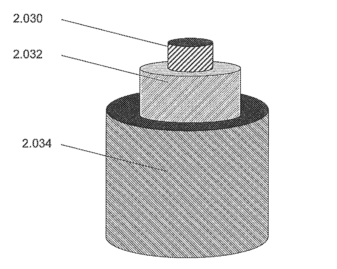
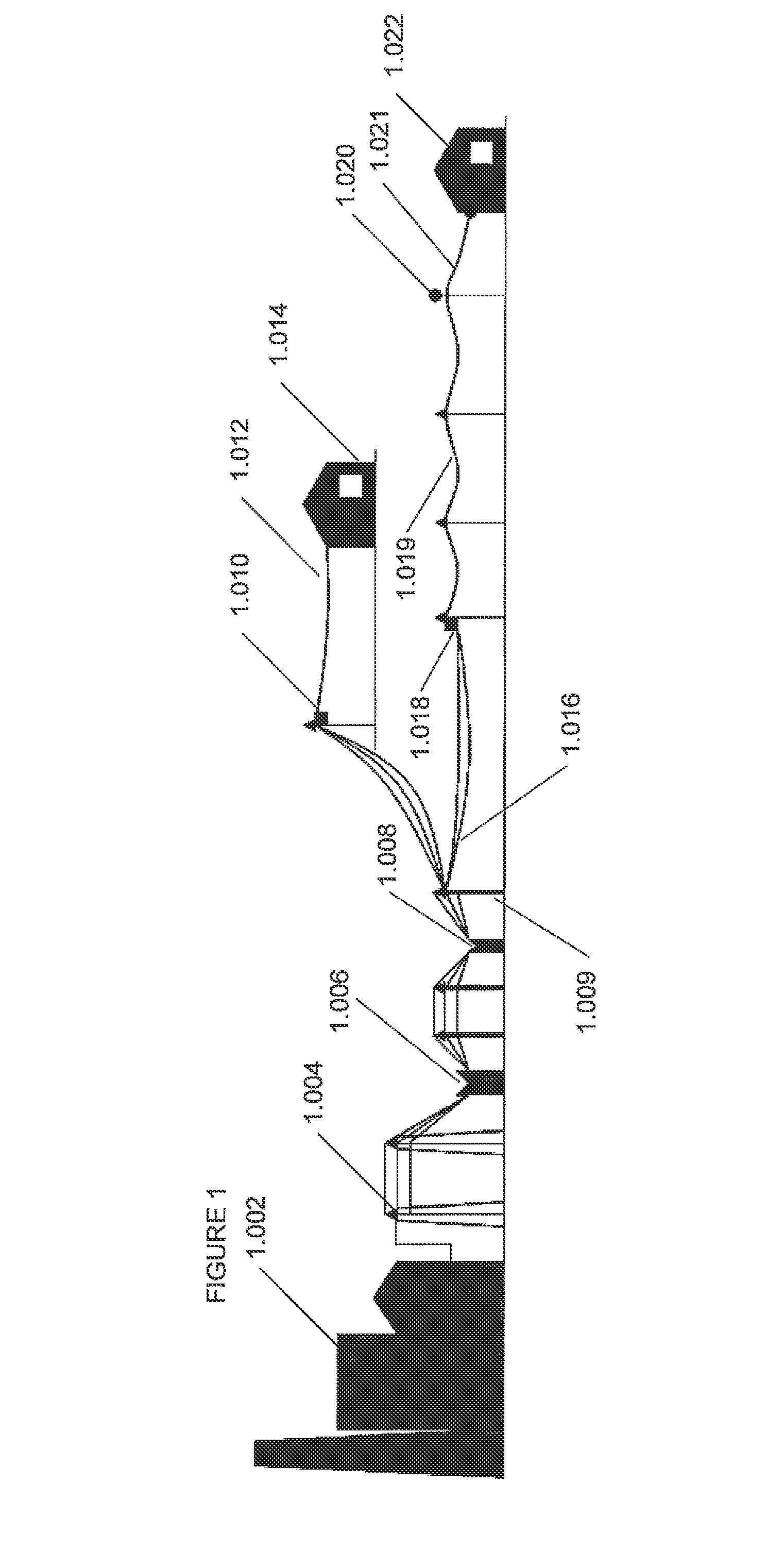
[0109]A first cable configuration using these materials has the following dimensions and characteristics:

3.6 mm diameter composite core;

0.462 mm thick aluminium (5.92 mm2);

1.0 mm thick XLPE / HDPE;

Total diameter: 6.52 mm;

Mass: 59.19 kg / km;

Breaking load: 23.27 kN

example 2

[0110]A second cable using the same materials can have the following dimensions and characteristics: 4.65 mm diameter composite core;

0.375 mm thick aluminium (5.92 mm2);

2.3 mm thick XLPE / HDPE;

Total diameter: 10 mm;

Mass: 120.5 kg / km;

Breaking load: 25.42 kN;

[0111]Example 1 has a lower wind loading due to the lower outer diameter.

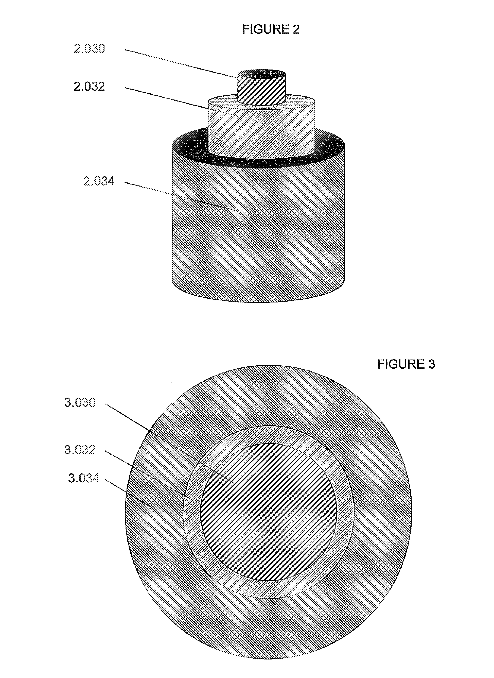
[0112]A cable made according to the invention has the advantage of having only three components, a core, a conductive layer, and a jacket. In addition, cables made according to the present invention have a higher strength to weight ratio than current aluminium steel cables. The cable also has good flexibility suitable for application as a suspended power line.

[0113]While the cable of this invention has been described in the context of a SWER line rural application, the cable can also be adapted use in other areas. For example, in suburban applications where the lines may come in contact with trees, the cable can be used in a 3 phase application. For such an ap...


PUM

PropertyMeasurementUnit
Thicknessaaaaaaaaaa
Thicknessaaaaaaaaaa
Diameteraaaaaaaaaa

Abstract

A cable adapted for suspension between poles in a single wire earth return application is composed of three elements; a core 2.030; a conductive layer 2.032 around the core, and a jacket 2.034 over the conductive layer. The core has high tensile strength to weight ratio and can be made of a composite material such as carbon fibre and epoxy. The conductive material can be aluminium. The jacket can be made from a material having electrical insulating properties. The conductive layer can be formed as a loose tube (7.072) around the core and drawn down to contact the outer surface of the core.

Description

FIELD OF THE INVENTION[0001]This invention relates to electrical cables.[0002]The invention is particularly suited for suspended power cables.BACKGROUND OF THE INVENTION[0003]The invention will be described in the context of a cable for use in a single wire earth return (SWER) electricity supply system such as may be used, for example, in a rural environment in which consumers are widely separated. The line voltage can be between about 11 KV and 33 KV. In Australia, 22 KV is commonly used.[0004]In some countries, such as Australia, much of the rural electricity supply is by Single Wire Earth Return (SWER) conductor systems or Single or two phases. SWER is a high voltage single phase distribution system using only one overhead line conductor; the circuit is completed through earth connections (much like the wiring in a car using the body and chassis as a return path to the battery “earth”).[0005]Such systems are difficult to adequately protect due to the high “impedance / resistance” o...

Claims


Application Information

Patent Timeline
IPC IPC(8): H01B9/00H01B7/02H01B3/30H01B7/17H01B1/02
CPCH01B9/008H01B7/17H01B7/0275H01B3/30H01B1/023H01B7/1825
Inventor LEE, MICHAELBARBER, KENNETH WILLIS
Owner OLEX AUSTRALIA
Why Eureka
Eureka Blog
Learn More