Automobile Ignition with Improved Coil Configuration

a technology of improved coil configuration and ignition system, which is applied in the direction of ignition circuit layout, basic electric elements, inductance, etc., can solve the problems of mechanical wear of breaker points, only obtaining a reasonable service life of the system, and mechanically timed ignition systems, so as to achieve greater spark signal, reduce inter-wire spacing, and reduce the effect of spacing

Inactive Publication Date: 2015-04-23
INTELLITRONIX
View PDF2 Cites 3 Cited by
  • Summary
  • Abstract
  • Description
  • Claims
  • Application Information

AI Technical Summary

Benefits of technology

[0020]In otherwise conventional ignition coils, a high-quality winding of the coil wires is attempted in which the wires are precisely arranged and densely arranged, above one another, so that there is a minimized spacing between them. In the present invention, given the generally rectangular cross sectional area of the coil windings (both primary and secondary), the intra-wire spacing can be further reduces.
[0021]Finally, the cylindrical coil wound core is contained within a plastic or metallic housing that is filled with a with an oil, asphalt or an epoxy potting resin to prevent moisture intrusion, eliminate air bubbles and provide inslulatin of the created thermal load.
[0022]It is an overall objective of the present inventive ignition coil to provide an automobile ignition system with the generation of a greater spark signal, or for delivering a spark signal with greater battery efficiency.

Problems solved by technology

Various disadvantages exist in these mechanically timed ignition systems.
These include, for example, the timing breaker points being subject to mechanical wear, as well as oxidation and burning at the contact surfaces from the constant sparking.
Such limitations result in obtaining only a reasonable service life of the system, and only if the power of the spark and ultimate engine speed are limited.
When gas velocity is high in the spark gap, the arc between the terminals is blown away from the terminals, making the arc longer and requiring more energy in each spark.
It is the creation of this spark which consumes the energy that was stored in the ignition coil's magnetic field.
Further, any efficiencies or losses created within the coil windings themselves can also tax or limit the coil's secondary output.
Because conventional wire windings have a generally round cross sectional area, the efficiency of packing these windings is limited, i.e. the given coil wire winding density is limited by the geometry and spacing of the packed windings.

Method used


Image

  • Automobile Ignition with Improved Coil Configuration
  • Automobile Ignition with Improved Coil Configuration
  • Automobile Ignition with Improved Coil Configuration

Examples


Embodiment Construction

[0040]The best mode for carrying out the invention is presented in terms of its preferred embodiment, herein depicted within the Figures wherein like reference numerals indicate the same parts throughout the several views.

1. Detailed Description of the Figures

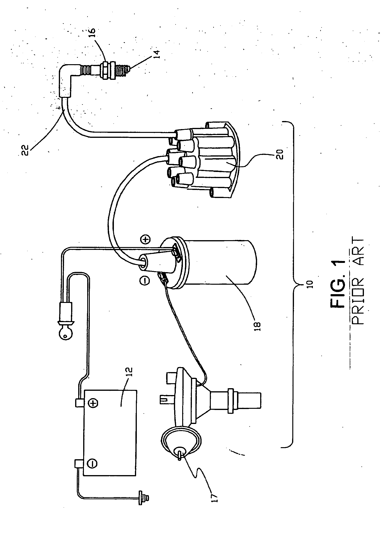
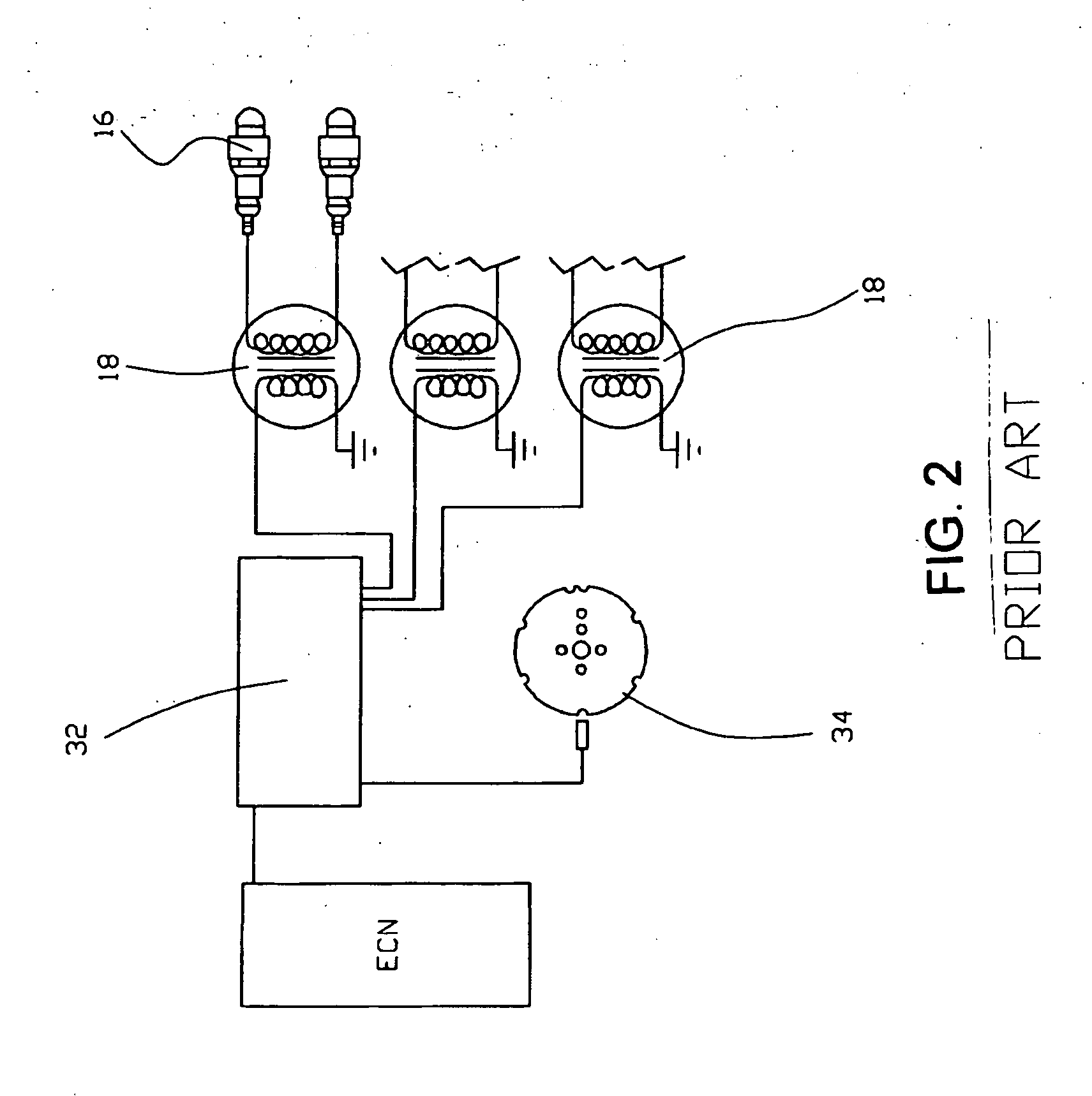
[0041]Referring now to FIG. 1 through FIG. 4, an overall automobile ignition system is generally noted as 10 according to the PRIOR ART. A typical 12-volt automotive ignition system 10 of a mechanically timed design is shown in FIG. 1, and operates by taking in a low voltage with high current from the car's battery 12 and changing it into a higher voltage with lower current to jump the spark plug gap 14 of the spark plug 16 to propagate combustion in the cylinder (not shown). This process is initiated by a trigger module 17, and results in the changing of low voltage current of the battery to a high voltage. This induction process takes place in the coil 18. From there, the high voltage spark is transferred to the distributor 2...


PUM

PropertyMeasurementUnit
voltageaaaaaaaaaa
linear lengthaaaaaaaaaa
lengthaaaaaaaaaa

Abstract

An automobile ignition coil for use in an ignition system is provided having a central cylindrical magnetic core element, and a secondary coil circumscribing the core element. The second linear length of copper wire has a cross sectional area in a rectangular, rhomboid or hexagonal regular polygonal shape. A primary coil circumscribes the secondary coil, and similarly has a cross sectional area in a rectangular, rhomboid or hexagonal regular polygonal shape.

Description

RELATED APPLICATIONS[0001]There are no previously filed, nor currently any co-pending applications, anywhere in the world.BACKGROUND OF THE INVENTION[0002]1. Field of the Invention[0003]The present invention relates to internal combustion engine ignition systems for generating a combustion spark for igniting the air-fuel mixture within the engine's cylinder and, more particularly, to an improved ignition system and ignition coil for generating and delivering a spark signal with greater efficiency.[0004]2. Description of the Related Art[0005]Ignition systems are well known in the field of internal combustion engines, and are used for igniting the fuel-air mixture within each cylinder. This creates combustion to drive the power stroke of the cycle. Prior generations of four-stroke engines used a mechanically timed electrical ignition system in which a distributor, containing a rotating cam (or rotor) driven by the engine's drive, directed the generated spark to each individual cylinde...

Claims


Application Information

Patent Timeline
Patent Type & Authority Applications(United States)
IPC IPC(8): H01F27/28H01F27/32H01F27/02H01F27/24
CPCH01F27/2823H01F27/022H01F27/324H01F27/24H01F38/12H01F2038/122F02P1/08H01F27/2455
Inventor SPIVAK, PAUL
Owner INTELLITRONIX
Why Eureka
Try Eureka