Zoom Lens And Image Pickup Device

a technology of image pickup and zoom lens, which is applied in the field of zoom lens, can solve the problems of increasing the effective diameter, increasing the thickness, and using the thinning method, and achieves the effect of reducing the size and favorably suppressing the various aberrations

Active Publication Date: 2015-04-23
KONICA MINOLTA INC
View PDF3 Cites 28 Cited by
  • Summary
  • Abstract
  • Description
  • Claims
  • Application Information

AI Technical Summary

Benefits of technology

[0059]The image pickup device according to the present invention is provided with the above-described zoom lens and the image pickup element for photoelectrically converting an image formed on an image pickup surface by the zoom lens. By using the zoom lens of the present invention, the image pickup device which achieves size reduction mainly in the thickness direction and favorably suppresses various aberrations can be obtained.

Problems solved by technology

In general, a variable-magnification optical system having the first lens group having a negative refractive power and a second lens group having a positive refractive power as in Patent Literatures 1 to 4 is advantageous in points that the thickness of the first lens group can be made small, that the number of constituting lenses can be made small, and that F-number of a wide-angle end can be made bright or fast, but since the first lens group has a negative refractive power, an effective diameter of the second lens group tends to become larger, and there is a problem that an increase in the effective diameter in a bending optical system portion directly leads to an increase of the thickness.
Particularly, the second lens group is often accompanied with an aperture stop and is a spot where an axial ray passes thickly, and thus, a thinning method used in the bending optical system portion in many cases in which a lens shape obtained by cutting a area not in use or a so-called oval shape is used instead of a circular shape symmetrical to the optical axis cannot be employed.
Moreover, since the second lens group has a large light beam diameter passing through the lens and moves for a long distance during magnification change from the wide-angle end to a telephoto end, decentration error sensitivity of the second lens group needs to be made as small as possible.
However, since the centering is an action for reducing axial coma aberration or one-side blur by decentering the lens with respect to the optical axis, a space needs to be ensured for centering in the second lens group, and there is a problem of size increase of the second lens group and hence thickening of a variable-magnification optical system.
However, in the variable-magnification optical system in Patent Literature 3, since the second lens group is constituted by one cemented lens of a lens having a positive refractive power and a lens having a negative refractive power, an aberration correcting capacity is low, and as a result, F-number becomes dark or slow.
Moreover, in Patent Literature 4, the second lens group is constituted by a cemented lens of a lens having a positive refractive power, a lens having a negative refractive power, and a lens having a positive refractive power in order from the object side, but since freedom of a lens surface is made small due to the cementing, a burden on an optical surface in contact with air becomes large, and the decentration error sensitivity of the surface becomes extremely high.

Method used


Image

  • Zoom Lens And Image Pickup Device
  • Zoom Lens And Image Pickup Device
  • Zoom Lens And Image Pickup Device

Examples


example 1

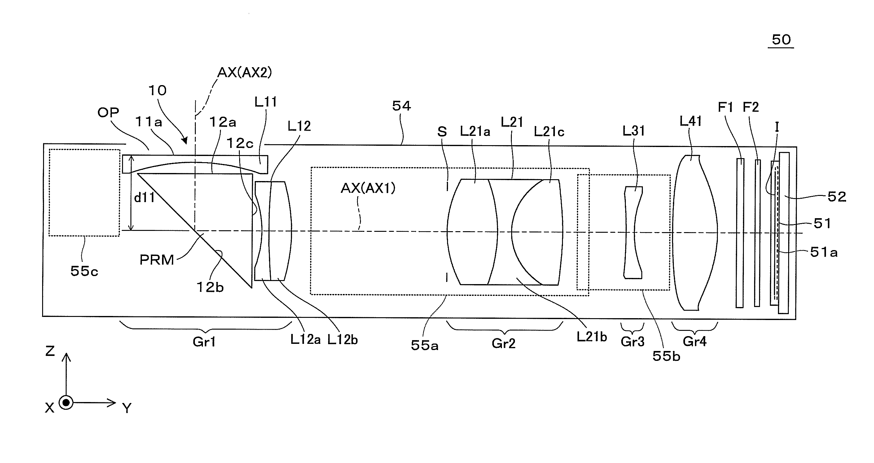
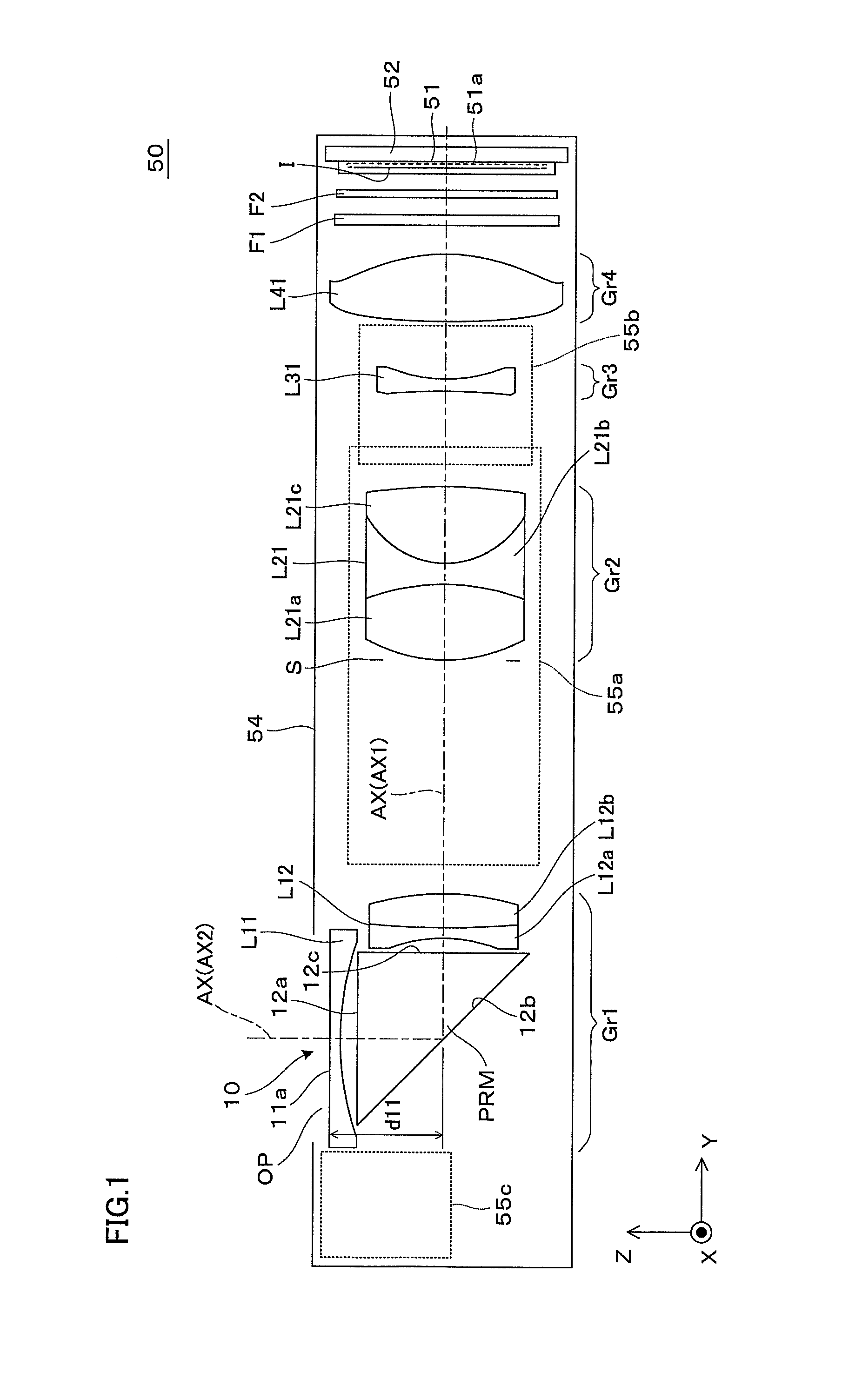
[0125]Basic features of a zoom lens in an example 1 are as follows:

Zoom ratio: 2.85

Lens entire length: 28.099

d11: 3.250

[0126]Lens data of the example 1 is shown in Table 1. In the following (including the lens data in Tables), a power multiplier of 10 (2.5×10−02, for example) is expressed by using E (2.5E-02, for example).

TABLE 1[Radius of curvature, surface distance and the like]Surf. NR(mm)D(mm)Ndνdeffective radius (mm) 1inf.0.3002.0010029.12.79 210.4460.4952.60 3inf.4.9112.0006925.52.55 4inf.0.4141.79 5−5.3820.3001.8830040.81.75 629.2500.9651.9228620.91.84 7−9.172d11.94 8(stop)inf.0.0001.98 9*5.4562.1591.8513540.12.0910−7.8460.6001.6989530.12.02113.0252.1911.5920167.01.9112*−13.303d21.8813*−14.7280.3501.5447056.21.8614*6.588d31.8915*33.0481.9311.5447056.23.0916*−6.4080.8223.1717inf.0.3001.5168064.23.0418inf.0.5003.0319inf.0.2101.5168064.22.9820inf.0.6402.97[Aspherical Coefficient]Ninth SurfaceK = 0.00000E+00, A4 = −0.65103E−03, A6 = 0.50692E−04,A8 = −0.13360E−04, A10 = 0.89604E−0...

example 2

[0134]Basic features of a zoom lens of an example 2 are as follows:

Zoom ratio: 2.85

Lens entire length: 27.523

d11: 2. 450

[0135]Lens data of the example 2 is shown in Table 4.

TABLE 4[Radius of curvature, surface distance and the like]Surf. NR(mm)D(mm)Ndνdeffective radius (mm) 1−13.5505.3502.0006925.52.88 2inf.0.1852.08 3−15.4800.4001.8348142.72.07 46.7101.1301.9228620.91.99 5529.000d11.91 6(stop)inf.0.0001.82 7*6.1851.8501.8513540.11.88 8−5.5000.4001.6989530.11.83 93.7201.7101.6188163.91.7510*−11.813d21.7011*19.6820.3001.5447056.21.7112*3.765d31.7013*−19.9451.7301.5447056.23.0114*−4.6751.3103.1415inf.0.3001.5168064.23.0316inf.1.0003.0217inf.0.2101.5168064.22.9818inf.0.6402.97[Aspherical Coefficient]Seventh SurfaceK = 0.00000E+00, A4 = −0.63372E−03, A6 = −0.74137E−04,A8 = 0.36010E−04, A10 = −0.10070E−04, A12 = 0.10203E−05Tenth SurfaceK = 0.00000E+00, A4 = 0.16722E−02, A6 = 0.13269E−03,A8 = −0.90310E−04, A10 = 0.13945E−04, A12 = −0.31151E−07Eleventh SurfaceK = 0.00000E+00, A3 = −0.95856...

example 3

[0142]Basic features of a zoom lens of an example 3 are as follows:

Zoom ratio: 2.85

Lens entire length: 28.017

d11: 3.521

[0143]Lens data of the example 3 is shown in Table 7.

TABLE 7[Radius of curvature, surface distance and the like]Surf. NR(mm)D(mm)Ndνdeffective radius (mm) 1inf.0.3001.9108235.33.05 28.5270.6962.80 3inf.5.0492.0006925.52.73 4inf.0.4451.98 5−5.9370.3001.6180063.41.95 6−91.2930.8301.9459418.01.92 7−13.577d11.90 8(stop)inf.0.0001.80 9*5.9052.0251.8208042.71.8610−6.8990.7001.6989530.11.82113.9591.7841.5920167.01.7612*−8.647d21.7513*−21.0830.3001.5447056.21.7514*5.160d31.7715*14.5482.3001.5447056.23.1716*−7.9381.6083.1417inf.0.2101.5168064.23.0018inf.2.99[Aspherical Coefficient]Ninth SurfaceK = 0.00000E+00, A4 = −0.82229E−03, A6 = 0.13210E−03,A8 = −0.69276E−04, A10 = 0.16105E−04, A12 = −0.13852E−05Twelfth SurfaceK = 0.00000E+00, A4 = 0.18236E−02, A6 = −0.12125E−03,A8 = 0.47657E−04, A10 = −0.12781E−04, A12 = 0.15336E−05Thirteenth SurfaceK = 0.00000E+00, A3 = −0.12209E−01, ...


PUM


Abstract

A first lens group includes a plano-concave and negative first lens, a catoptric element having a flat object side surface and a flat image side surface, and a first cemented lens, for example. Here, the first cemented lens includes a negative second lens and a positive third lens in order from an object side. A second lens group includes an aperture stop and a positive second cemented lens, for example. The second cemented lens includes a positive fourth lens, a negative fifth lens, and a positive sixth lens in order from the object side. A zoom lens satisfies a conditional expression 1.59<n21<2.20, assuming that a value n21 indicates refractive index of the fourth lens on a side closest to an object in the second lens group.

Description

[0001]This application claims a priority under the Paris Convention of Japanese patent application No. 2013-217921 filed on Oct. 18, 2013, the entirety of which is incorporated herein by references.TECHNICAL FIELD[0002]The present invention relates to a zoom lens composed of a plurality of lens groups and performing magnification change by changing intervals between the lens groups in an optical direction and an image pickup device provided with the zoom lens.BACKGROUND ART[0003]With recent performance improvement and size reduction of an image pickup device using a solid-state imaging element such as a CCD (Charge Coupled Device) type image sensor or a CMOS (Complementary Metal Oxide Semiconductor) type image sensor and the like, a mobile phone and a portable information terminal provided with an image pickup device has begun to spread in recent years. Since restriction on size and cost is extremely strict in these devices, an image pickup device provided with a small-sized solid-s...

Claims


Application Information

Patent Timeline
Patent Type & Authority Applications(United States)
IPC IPC(8): G02B13/00H04N5/232G02B27/64G02B15/177G02B17/08
CPCG02B13/0065G02B15/177G02B17/0896H04N5/23296G02B17/0856G02B13/009G02B27/646G02B15/144511
Inventor OZAKI, YUICHIYAMASHITA, ATSUSHI
Owner KONICA MINOLTA INC
Why Eureka
Try Eureka