Purge system for reductant delivery unit for a selective catalytic reduction system

a technology of selective catalytic reduction and purging system, which is applied in the direction of exhaust treatment, lighting and heating apparatus, combustion types, etc., can solve the problems of high nitrogen oxide emissions of lean-burn engines, damage to injection units, and insufficient efficiency of this method, so as to reduce the sealing load of existing sealing elements, increase the amount of time, and maximize the fluid volum

Active Publication Date: 2015-04-30
VITESCO TECH USA LLC
View PDF7 Cites 14 Cited by
  • Summary
  • Abstract
  • Description
  • Claims
  • Application Information

AI Technical Summary

Benefits of technology

[0015]This cycle may then be repeated as many times as necessary. It is therefore an object of this invention to maximize the fluid volume evacuated from the injector. It is another object of this invention to provide an additional sealing barrier to reduce the sealing load of the existing sealing elements. It is another object of the invention to increase the amount of time that the gas flow rate is high and efficient for scavenging the injector, due to the high level of generated vacuum. It is yet another object of this invention to allow for the trapped fluid in the off-axis volumes (such as the volume bounded by the injector cup and the main gas stream) to flow back into the main gas stream—this permits the next wave of high intensity gas flow to remove this fluid which was previously trapped in the inaccessible volumes of the injector.

Problems solved by technology

Lean-burn engines exhibit high levels of nitrogen oxide emissions (NOx), that are difficult to treat in oxygen-rich exhaust environments characteristic of lean-burn combustion.
This expansion may cause damage to the injection unit, therefore, injection systems typically purge the injection unit when the engine shuts down to remove the fluid contained therein.
It has been found that the efficiency of this method is not 100%, i.e., a certain amount of fluid remains in the injector unit.
Although the amount of remaining fluid may not always be sufficient to risk damage to the injector upon freezing (expansion volume is available for the expanding ice), a risk remains that during engine hot soaks, the remaining fluid could be exposed to high temperature.
This high temperature exposure could result in the decomposition of the AUS-32 which would also cause damage to the injection unit.
However, in some injectors, there is a potential leak path for the AUS-32 past the installed O-ring which cooperates with the injector cup to provide a sealing function.
Although this sealing path created by the 0-ring is typically sufficient for liquids, it has been found that AUS-32 solution is prone to breaching seals of this type in the form of creeping urea crystals.

Method used


Image

  • Purge system for reductant delivery unit for a selective catalytic reduction system
  • Purge system for reductant delivery unit for a selective catalytic reduction system
  • Purge system for reductant delivery unit for a selective catalytic reduction system

Examples


Embodiment Construction

[0022]The following description of the preferred embodiment(s) is merely exemplary in nature and is in no way intended to limit the invention, its application, or uses.

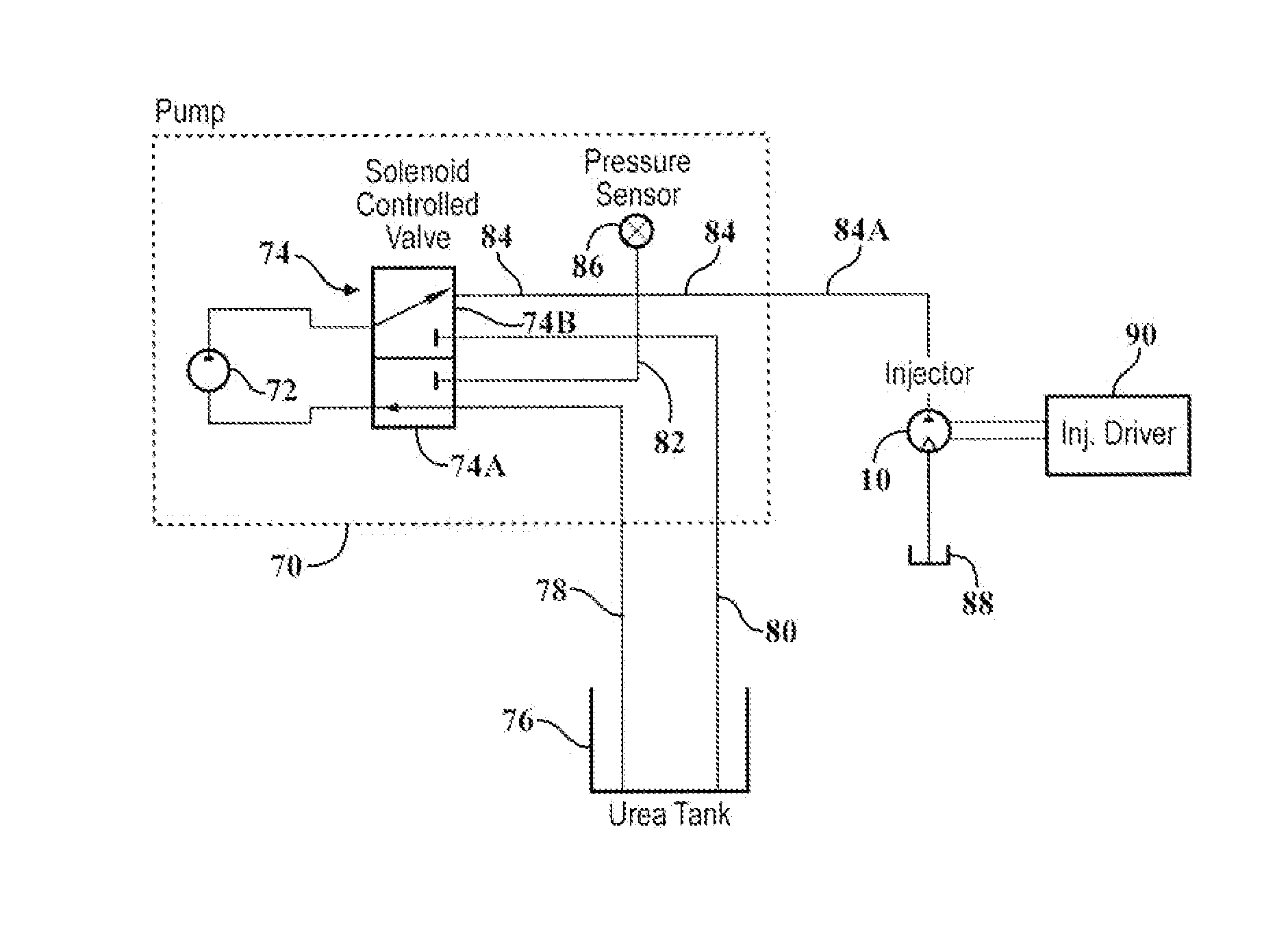
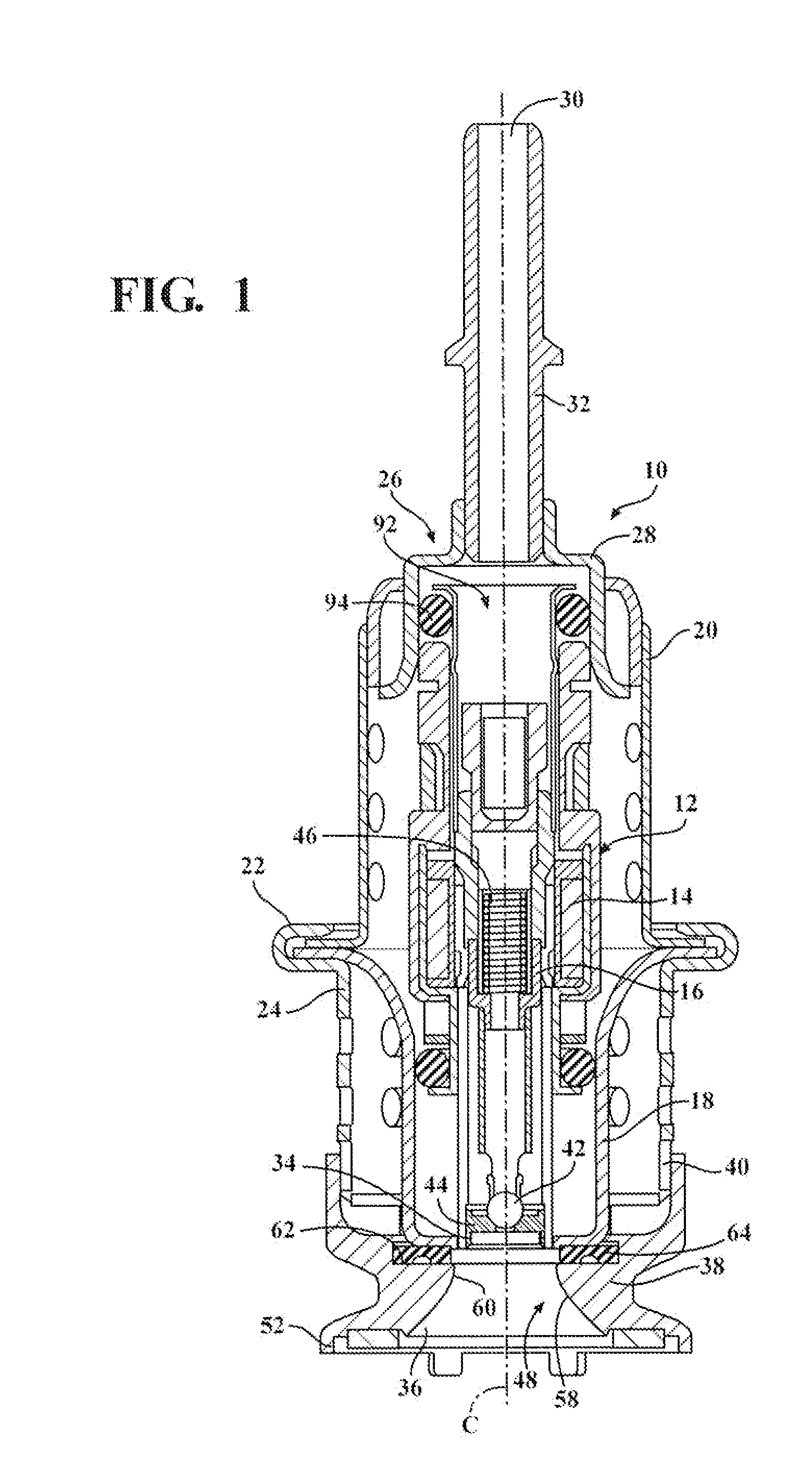
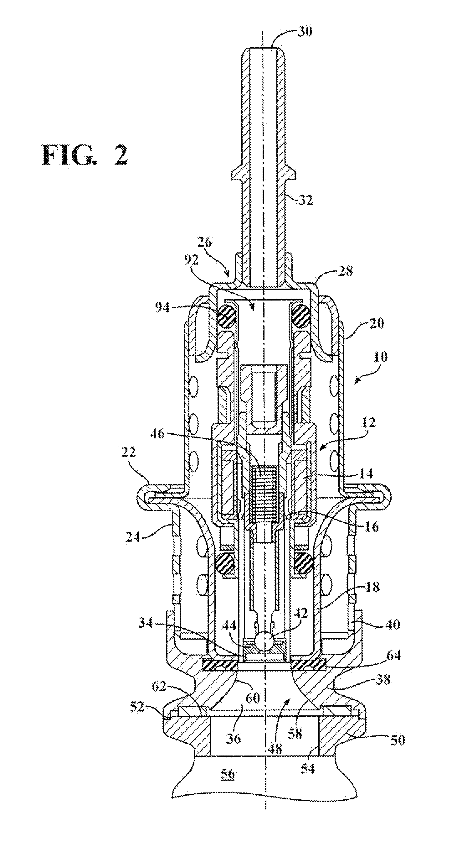
[0023]A reductant delivery unit (RDU) having a valve portion which incorporates multiple vacuum generating sequences during a purge event is shown in the Figures generally at 10. The RDU 10 includes a solenoid fluid injector, generally indicated at 12, that provides a metering function of fluid and provides the spray preparation of the fluid into the exhaust path of a vehicle in a dosing application. Thus, the fluid injector 12 is constructed and arranged to be associated with an exhaust gas flow path upstream of a selective catalytic reduction (SCR) catalytic converter. The fluid injector 12 is preferably an electrically operated, solenoid fuel injector. Thus, the injector 12 has a coil 14 and a movable armature 16.

[0024]The fluid injector 12 is disposed in an interior carrier 18. An injector shield 20 is coupled to ...


PUM


Abstract

A purge procedure which is part of an injector, that may be used as part of a reductant delivery unit (RDU), where the RDU is part of a selective catalytic reduction system for injecting diesel exhaust fluid into an exhaust system, to control exhaust emissions. The RDU delivers a reductant carrier to the engine exhaust system. The purge process includes a control strategy to improve the quality of the purge cycle (i.e., increase the amount of fluid evacuated). The sequence of the purge event is adjusted in order to generate a strong vacuum in the fluid supply line and the injector—this enhances the efficiency of the purge by increasing the initial flow rates through the injector. However, upon opening the injector, the pressure inside the fluid path increases to a level just below the ambient pressure outside the injector, therefore the gas flow rate is substantially reduced.

Description

FIELD OF THE INVENTION[0001]The invention relates generally to a purge procedure for a reductant delivery unit which is part of a selective catalytic reduction system.BACKGROUND OF THE INVENTION[0002]New emissions legislation in Europe and North America is driving the implementation of new exhaust aftertreatment systems, particularly for lean-burn technologies such as compression-ignition (diesel) engines, and stratified-charge spark-ignited engines (usually with direct injection) that are operating under lean and ultra-lean conditions. Lean-burn engines exhibit high levels of nitrogen oxide emissions (NOx), that are difficult to treat in oxygen-rich exhaust environments characteristic of lean-burn combustion. Exhaust aftertreatment technologies are currently being developed that treat NOx under these conditions.[0003]One of these technologies includes a catalyst that facilitates the reactions of ammonia (NH3) with the exhaust nitrogen oxides (NOx) to produce nitrogen (N2) and water...

Claims


Application Information

Patent Timeline
Patent Type & Authority Applications(United States)
IPC IPC(8): F01N3/20
CPCF01N3/2066F01N3/208F01N2610/02F01N2610/1433F01N2610/144F01N2610/1453F01N2610/1493Y02T10/12F01N9/00F01N2610/14F01N2610/1473
Inventor VAN VUUREN, WILLEM NICOLAAS
Owner VITESCO TECH USA LLC
Why Eureka
Try Eureka