Gravity urinary drainage system

US20150126975A1Inactive Publication Date: 2015-05-07SIENNA COLORADO SOLUTIONS

Image

  • Gravity urinary drainage system
  • Gravity urinary drainage system
  • Gravity urinary drainage system

Examples


Embodiment Construction

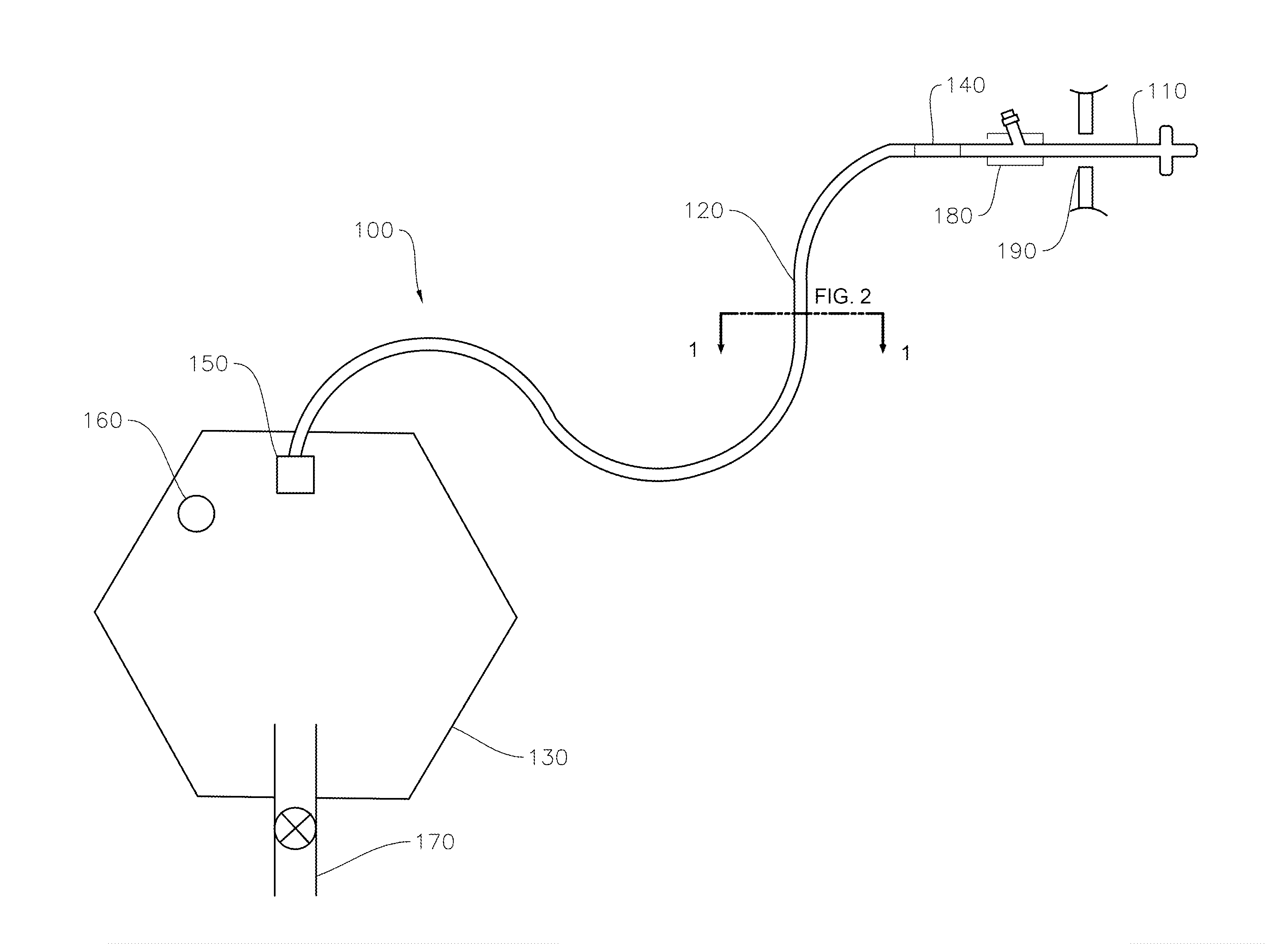
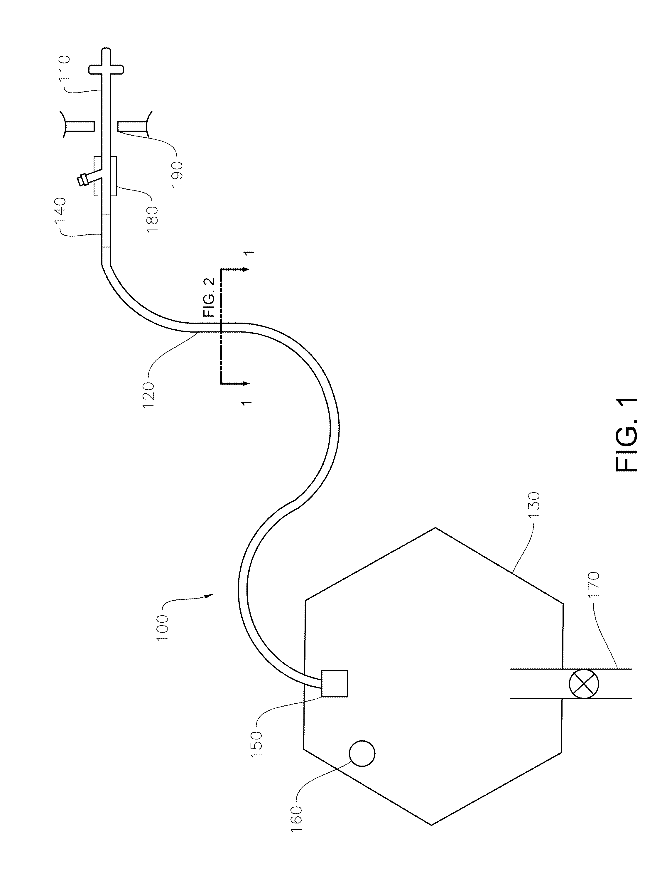
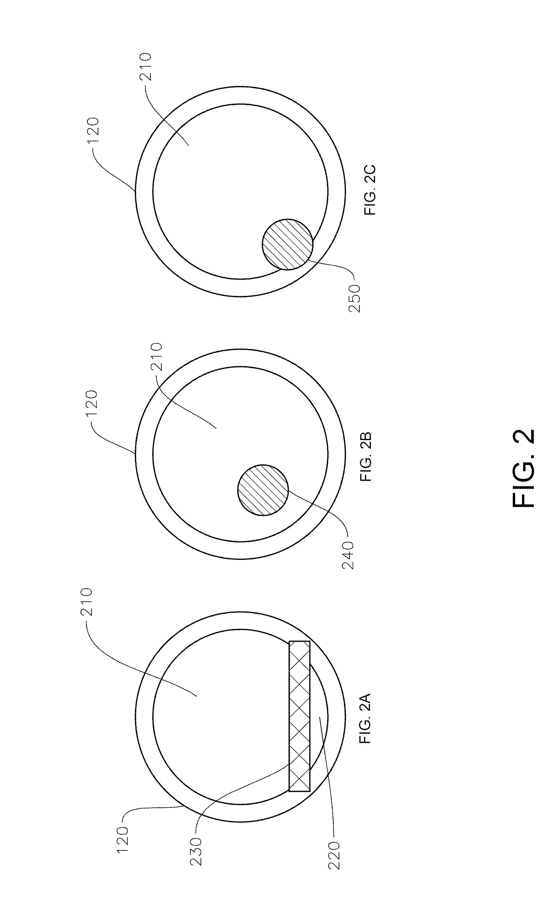
[0047]Embodiments of the present invention are hereafter described in detail with reference to the accompanying Figures. Although the invention has been described and illustrated with a certain degree of particularity, it is understood that the present disclosure has been made only by way of example and that those skilled in the art can resort to numerous changes in the combination and arrangement of parts without departing from the spirit and scope of the invention.

[0048]The following description with reference to the accompanying drawings is provided to assist in a comprehensive understanding of exemplary embodiments of the present invention as defined by the claims and their equivalents. It includes various specific details to assist in that understanding but these are to be regarded as merely exemplary. Accordingly, those of ordinary skill in the art will recognize that various changes and modifications of the embodiments described herein can be made without departing from the s...


PUM


Abstract

An improved fluid drainage system is comprised of a transfer tubing that includes a secondary axial compartment for the movement of air. This secondary lumen of the transfer tubing includes a gas permeable material which will allow the transport of air, while repelling fluid. The secondary lumen transports air from any section of the transfer tubing to the collection bag, as a means of eliminating and equating pressurized air pockets that can result in flow retardation. The urinary drainage system of the present invention remains a closed system, but with an internal venting system to improve flow distally from the body.

Description

CROSS-REFERENCE TO RELATED APPLICATIONS[0001]The present application relates to and claims the benefit of priority to U.S. Provisional Application No. 61 / 900,169, Gravity Urinary Drainage System, filed Nov. 5, 2013 which is hereby incorporated by reference in its entirety for all purposes as if fully set forth herein.BACKGROUND OF THE INVENTION[0002]1. Field of the Invention[0003]Embodiments of the present invention pertain to field of endeavor of medical drainage devices and more particularly to gravity driven urinary drainage devices and methodology.[0004]2. Description of Relevant Art[0005]The indwelling urinary drainage catheter, also commonly called the Foley catheter, is a well-accepted medical device frequently used in hospital and clinical settings. It is considered to be an essential part of a patient's medical care, but also been called an often-ignored and omnipresent device. The indwelling catheter is comprised of the Foley catheter (catheter tip), transfer tubing, and c...

Claims


Application Information

Patent Timeline
07 May 2015
Publication
US20150126975A1
IPC
A61F5/44
CPC
A61F5/4404; A61M1/83
Inventors
WUTHIER, PHIL