Sensor System for Environmental Impact Monitoring

Inactive Publication Date: 2015-05-14
WOODS HOLE OCEANOGRAPHIC INSTITUTION
View PDF7 Cites 7 Cited by
  • Summary
  • Abstract
  • Description
  • Claims
  • Application Information

AI Technical Summary

Benefits of technology

[0010]This invention features a self-contained and economical system that repeatably and consistently measures at least one type of electromagnetic emission, such as optical radiation or narrow-band EM field, and at least

Problems solved by technology

Currently available monitoring systems tend to be uni-modal, often hand held and weather-intolerant and are not useful for taking persistent, calibrated, time-stamped readings across multiple modalities.
A wind turbine generates acoustic noise, shadow flicker, an EM field, and a measurable amount of ground vibration.
Similarly, aquatic hydrokinetic systems produce an acoustic signal and may cause light field modifications, and in

Method used


Image

  • Sensor System for Environmental Impact Monitoring
  • Sensor System for Environmental Impact Monitoring
  • Sensor System for Environmental Impact Monitoring

Examples


example 1

Infrasound & Measurements at a Wind Turbine

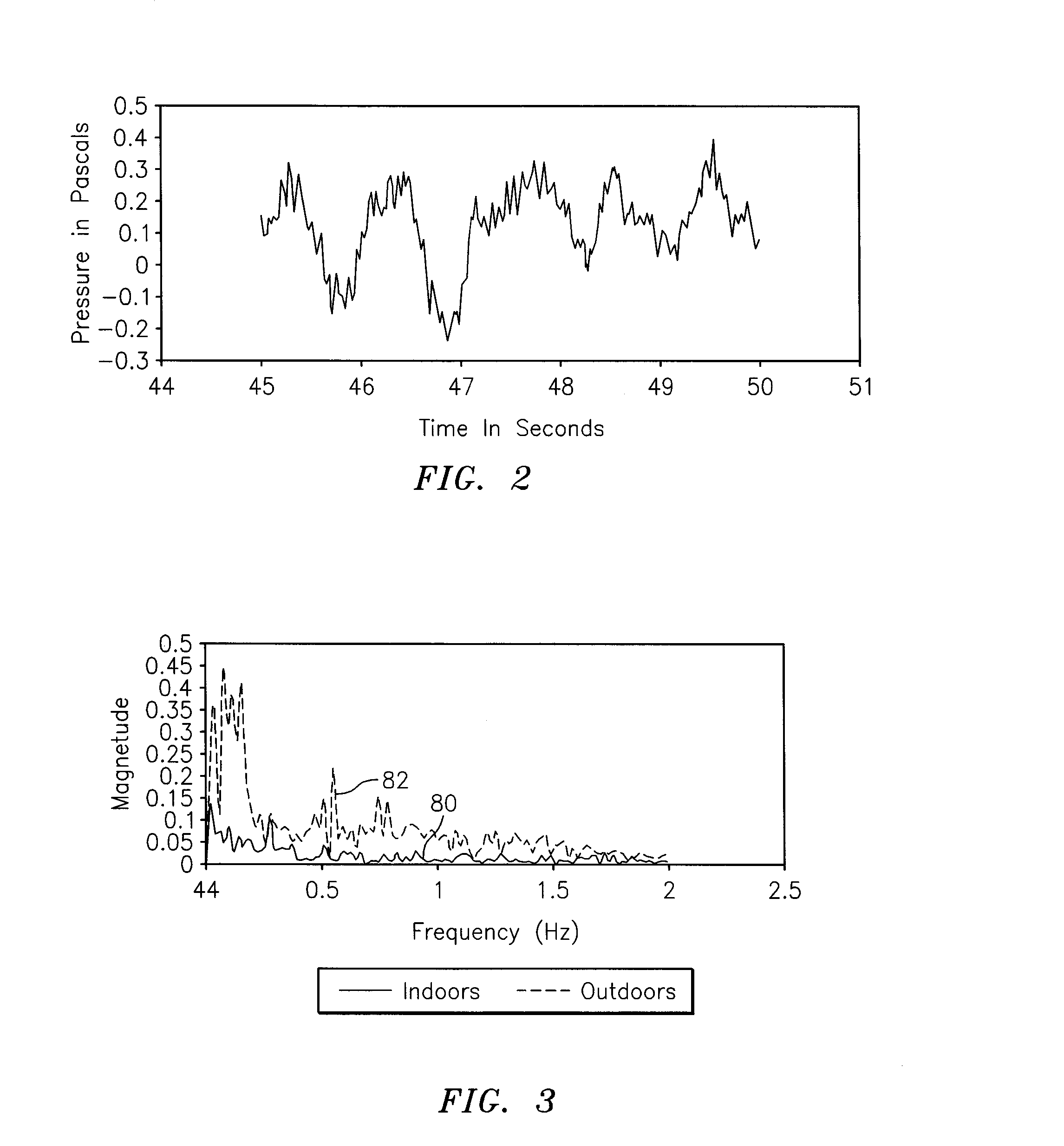
[0066]FIG. 2 depicts the results of measurements made of infrasound signal showing a 1.3 second blade pass period. The inventive device was placed at a distance of 100 meters from a 1.65 MW Vesta wind turbine.

[0067]Instead of the preferred large diaphragm capacitive pressure sensor, the prototype employed in this example utilized a solid state differential pressure transducer similar to those used in medical instrumentation. A custom analog circuit was used to extend the usable range of this device. For the acoustic sensor, a downward-slanted, non-compliant surface was installed to reflect horizontally-directed acoustic waves in an upward direction towards a receiving microphone element.

example 2

Use of the Sensor Array at a Residence

[0068]FIG. 3 shows infrasound measurement results from a dual sensor prototype inventive device to measure infrasound both inside, spectrum 80, and outside, spectrum 82, a residence over a frequency range of 0.0 Hz to 2.0 Hz.

example 3

Use of the Sensor Array to Quantify Flicker Effect

[0069]FIG. 4 shows blade-induced flicker measurement results from a dual sensor prototype inventive device to measure both direct 2π radiative signal, profile 92, and 4π spherical collector signal, profile 90.

[0070]A monitor system 100 according to the present invention is illustrated in FIG. 6 having four multi-modal sensor units S1, S2, S3 and S4 spaced about installation I, such as a wind turbine, at distance D1 for sensor S1, at distance D1+D2 for sensor S2, at distance D3 for sensor S3, and at distance D4 for sensor S4, respectively. Each of distances D1-D4 are the same in one construction and, in other constructions, differ from each other. In some constructions, the distances D1-D4 are selected based on the height and / or strength of emissions from installation I. Arrow P represents the direction of flow of a prevailing wind for terrestrial sites and of a prevailing current for underwater sites; typically, sensor S1 will experi...


PUM


Abstract

A self-contained monitor array for measuring at least one type of electromagnetic emission and at least one type of mechanical wave emission from a marine-based and/or terrestrial human activity or installation such as alternate energy sources. A multi-modal monitor system includes at least two such arrays, at least one clock, and at least one data storage unit.

Description

CROSS-REFERENCE TO RELATED APPLICATION[0001]This application claims priority to U.S. Provisional Application No. 61 / 903,162 filed 12 Nov. 2013 and to U.S. Provisional Application No. 62 / 037,487 filed 14 Aug. 2014.FIELD OF THE INVENTION[0002]This invention relates to measurement of emissions from selected sites and more particularly to multi-modal monitoring of such emissions.BACKGROUND OF THE INVENTION[0003]Continuous quantitative monitoring of sound, light, vibration and / or EM fields is critical for evaluating the environmental impact of a wide variety of mechanical installations. Currently available monitoring systems tend to be uni-modal, often hand held and weather-intolerant and are not useful for taking persistent, calibrated, time-stamped readings across multiple modalities. The inventive multi-modal environmental monitor described herein is easy to use, low in cost and portable for continuous and simultaneous quantitative monitoring of three or four modalities at a single in...

Claims


Application Information

Patent Timeline
IPC IPC(8): G01M99/00G01N29/14
CPCG01N29/14G01M99/00F03D17/00F05B2270/333F05B2270/81G01N29/46G01N2291/2693Y02E10/72
Inventor FUCILE, PAUL DOMINICMCDONALD, GLENN ELWINHOBART, EDWARD LEO
Owner WOODS HOLE OCEANOGRAPHIC INSTITUTION
Why Eureka
Try Eureka